A CPW-fed broadband circularly polarized slot antenna detailed tutorial
As an important branch of antenna theory and application, circular polarization technology is widely used in communication and electronic countermeasures. At present, the circularly polarized antenna is mainly based on a microstrip antenna, but the microstrip antenna has more approximate processing, so the accuracy of the design is not so good, and the frequency band of the microstrip antenna is also narrow, and the ordinary single feed circle The bandwidth of a polarized microstrip antenna is generally less than 3%, and the dispersion of the dielectric substrate also affects the accuracy of the resonant frequency. Coplanar waveguide (CPW)-fed planar antennas are easy to integrate with active devices to form multiple feed modes because their radiating elements and feeding units are in the same plane. In recent years, more attention has been paid, but most of them have received much attention. Circularly polarized broadband antennas are fed by microstrip lines, and reports on circularly polarized planar antennas fed by CPW are less common.
2 antenna designThe structure of the antenna is as shown in Fig. 1. A square slit with a side length L is opened on a square dielectric plate having a thickness h, a dielectric constant ε, and a side length G, and two connected elliptical metals are extracted in the slit. sheet. The antenna is fed with a 50 Ω CPW, the CPW excitation length is L3, the width is Wf, the length of the extended excitation strip is L2, and the width is the dielectric material of the substrate selected h=0.8 mm, ε=4.6, and the side length G=60 mm. Wf = 3.1 mm, g = 0.3 mm.
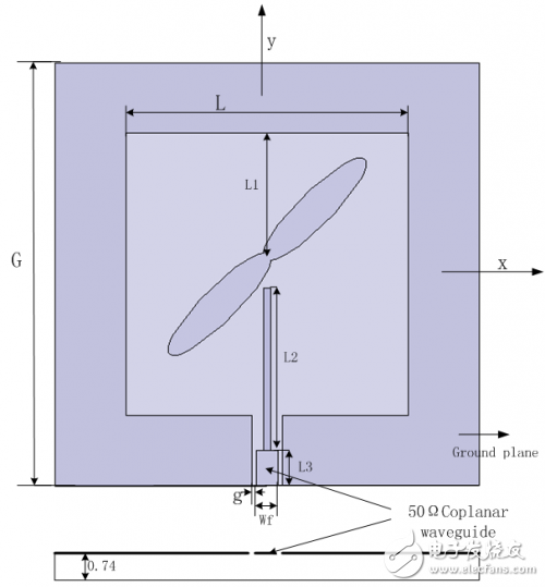
Figure 1 Antenna structure diagram
The HFSS software is used to analyze the position and size of the elliptical metal sheet, and the optimal structure size of the antenna is optimized. The final structural parameters are L=40mm, L1=17.5 mm, L2=23mm, L3=5mm, two main radii of 10mm, elliptical metal sheets with a ratio of 0.25 are connected, placed on the upper part of the diagonal of the square slit.
3 Simulation and measured resultsFigure 2 shows the comparison of the measured results of the antenna shaft ratio with the HFSS simulation results. The measured 3dB axial ratio band is 2.32-2.57GHz, and the relative bandwidth is 10.4%. Figure 3 shows the curve of the antenna S-parameter as a function of frequency. The return loss "-10dB band is 2.38-2.76 GHz, which is 15.5%. It can be seen that the antenna has a wide impedance and axial ratio bandwidth.
Figure 4 shows the gain simulation curve for the antenna. As can be seen from the figure, the antenna is between 1.5-3.0 GHz, and the gain variation is "1 dB, which has a wide 1 dB gain bandwidth. In the 3dB axial ratio bandwidth (2.32-2.57GHz), the gain of the antenna is between 2dB and 3dB.
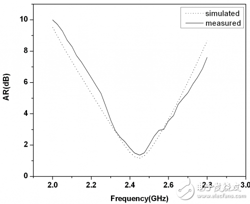
Figure 2 Axis ratio measurement results and simulation results of the antenna
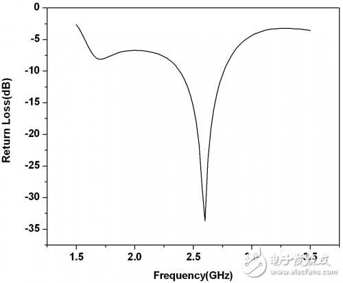
Figure 3 Antenna return loss simulation results
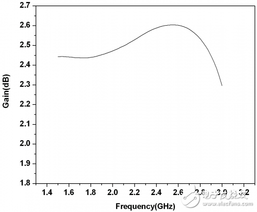
Figure 4 Antenna gain simulation results
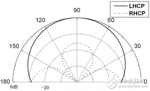
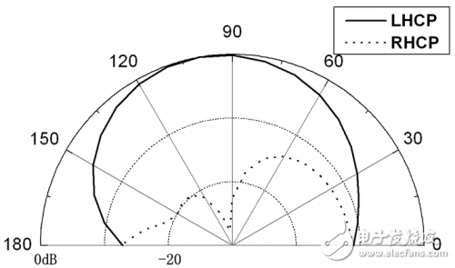
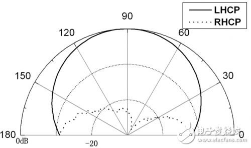
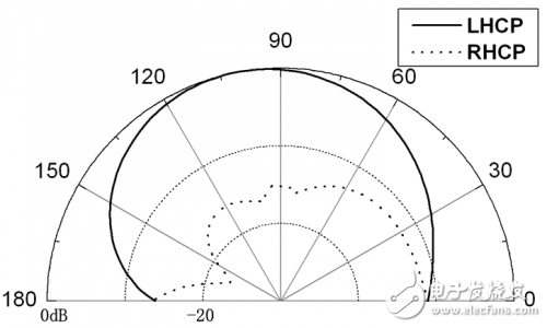
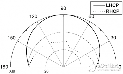
Figure 5 (a), (b), Figure 6 (a), (b) and Figure 7 (a), (b) show the antenna at x2, yz at 2.32 GHz, 2.45 GHz and 2.57 GHz, respectively. The direction of the map.
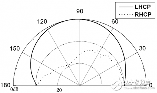
( a) xz plane
(b) yz plane
Figure 5 Antenna at 2.32GHz
(a) xz plane
(b) yz plane
Figure 6 Antenna at 2.45GHz
(a)xz plane
(b) yz plane
Figure 7 Antenna at 2.57GHz
The circularly polarized antenna given in this paper radiates a left-handed circularly polarized wave. To achieve right-handed circular polarization, it is only necessary to place the elliptical metal piece above the diagonal of the opposite direction. It can be seen that the antenna can conveniently realize left and right circular polarization.
4 ConclusionThis paper presents a design method for a broadband circularly polarized slot antenna fed by CPW. A pair of elliptical patches connected to excite a pair of orthogonal degenerate modes with a phase difference of 90o to achieve circular polarization. At the same time, it is convenient to change the direction of circular polarization by simply placing the patch on the other diagonal of the rectangular slit. The antenna has a simple structure, and the test result shows that the axial specific bandwidth is 10.4%. In this frequency band, the gain variation of the antenna is less than 1 dB, so the antenna has good circular polarization characteristics.
Universal Meter,Multi-Function Multimeter,Electronic Multimeter,Electronic Volt-Ohm-Ma Meter
YINTE TOOLS (NINGBO) CO., LTD , https://www.yinte-tools.com