
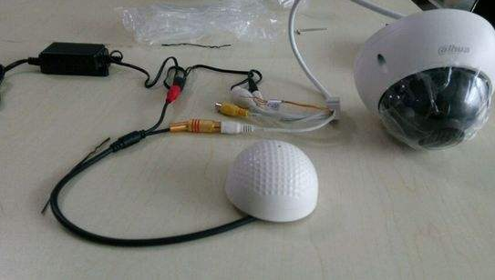
A pickup is an accessory used to collect sound from the scene, an electroacoustic instrument that amplifies sound by receiving sound vibrations.
The pickup is usually 3 wires or a binding post, nothing more than the positive pole of the power supply, the positive pole of the audio and the common ground. The back-end accessory is usually a hard disk recorder (DVR) or recording device. The pickup is powered separately. The remaining two lines are audio outputs that interface with the audio input of the back-end recording device.
Try to have RVVP audio shielding cable, it is strongly not recommended to use the network cable. In addition, the power supply should use a regulated power supply (transformer), which is a copper coil, which is very heavy in the hand. Try not to use a switching power supply. Otherwise it may greatly affect the quality of the sound.
The main function of the monitoring pickup is to convert the sound signal of the scene into an electrical signal for transmission to the amplifier for amplification. It is the front-end equipment in the sound monitoring system, and its quality will directly affect the sound quality of the entire monitoring system. The following describes a simple and practical monitoring and pickup circuit that is widely used in engineering practice. The structure of the circuit is different from the general amplifying circuit. The circuit design reduces the influence of the length of the connection between the pickup on the rear stage load, the distributed capacitance on the connection line, and the load input impedance on the quality of the pickup. Through careful design, the circuit has the advantages of low noise, good sound quality, low power consumption and good stability.
First, the structure of the circuit and work intention
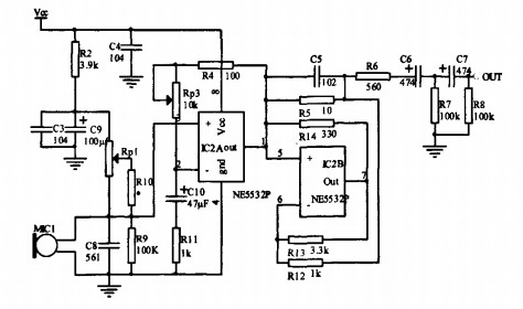
The whole circuit is composed of a power supply circuit and a main circuit. The main circuit is composed of a microphone input circuit, a voltage amplifying circuit, a current amplifying circuit and a filtering circuit.
The power circuit provides a "clean" operating power supply for the main circuit portion. The circuit uses a three-terminal integrated voltage regulator 78L09 to regulate the input power supply voltage, and cl and c2 filter the power supply. LED1 and R1 form a power indicating circuit. The addition of VDI in this circuit has power reverse polarity protection.
The main function of the monitoring pickup is to use the microphone to pick up the sound signal and amplify it to a certain amplitude output for transmission to the audio monitoring system for further amplification processing. The circuit is composed of an electret microphone MI CI and biasing elements R2, c3, C9, Rpl, RI O, R9 and c8 to form a microphone input circuit, and an operational amplifier IC2A and peripheral components Rp3, R4, C10, and R11 form a voltage amplifying circuit. IC2B and its peripheral components R12, R13, R14, R5, R6, and C5 form a current drive circuit, and R6, c6, R7, c7, and R8 constitute a filter output circuit. In the main circuit, c4 is placed near the circuit power supply pin to short-circuit the AC noise, further reducing the ripple of the power supply.
The microphone bias circuit needs to be carefully considered in the design of the monitor pickup of the built-in microphone: the bias voltage of the commonly used electret microphone is directly biased from the power supply to the microphone. In this case, the bias voltage is The noise picked up on the line that reaches the microphone and the noise in the power supply are directly coupled into the output signal of the microphone, which increases the noise of the output. The microphone bias of this circuit uses R2 and c3, c9 to form an R-c filter to attenuate the noise caused by the bias voltage, and install the microphone close to the input of the amplifier circuit to reduce the noise. Rpl, RIO, and R9 provide bias voltages for electret microphones. By adjusting Rpl, the electret microphone is given a bias voltage of 2 to 3 volts, which also adjusts the sensitivity of the circuit. The amplification effect in this circuit is mainly accomplished by the amplifier IC2 forming an amplifying circuit. The circuit is patented with the Japanese Matsushita subsidiary Te chni cs from analog audio amplifier circuits and Aubrey. The class S amplifier circuits designed and named by Dr. Aubr ey Sa ndma n are similar in principle. Their common feature is that the circuit consists of a voltage amplifier and a current amplifier, and the two amplifiers are coupled by a bridge.
This circuit is identical in structure to the S-type amplifier, except that the parameters are fine-tuned. Using this circuit structure and parameters allows the voltage-controlled amplifier to operate at an equivalent load-free state, so that even with a very strong load, even a composite dynamic impedance with different voltage and current waveforms, the amplifier can still output the best The characteristic, that is to say, the equivalent no-load characteristic is independent of the type and size of the actual load, so that the length of the connection between the pickup and the rear stage load, the size of the distributed capacitance on the connection line, and the load input impedance pair can be eliminated. The impact of sound quality. From the main circuit, IC2A and peripheral devices in the amplifying circuit form a class A current amplifier with a very limited load capacity, followed by a class II current amplifier composed of IC2B and its peripheral components.
IC2A and IC2B are coupled by a Wheatstone bridge composed of R12, R13, R14, and R5. In this circuit, IC2A constitutes the form of the non-inverting input of the fishing voltage amplifier, which is equivalent to a "lighter" load for the microphone, so the influence on the microphone is small. The voltage amplification of this stage is by the formula R4+Rp3, Decide. The current amplifier composed of I C2B is only inconsistent with the s-type amplification circuit of R14, and its amplification capability is similar to that of the s-type amplification circuit. The selection of the s amplifier circuit parameters makes the bridge in equilibrium, namely: R12XRl 4 = R13XR5; and the selection of the parameters in this circuit, the bridge is not in equilibrium.
Through simulation analysis, we can conclude:
(I) Increasing the resistance of R14 will increase the frequency characteristics of the circuit, but the current amplification capability will decrease when unbalanced. When designing the circuit, consider choosing the appropriate resistor. It is considered that no large power is required due to the output of the monitor circuit. Therefore, the shortcoming of the output power of the circuit is not an important issue.
(2) The output current of the voltage amplifier at the bridge balance and unbalance is small and does not change much, so the circuit still has the characteristics of this type of circuit.
The output of the monitoring pickup adds a two-stage Rc high-pass filter composed of c6, R7, c7, and R8 to filter out the high-frequency components in the signal, and the capacitor acts as a blocking function, so that the circuit achieves better performance. .
Second, the choice of components and operation of the circuit in the selection of components should pay attention to the following points:
(I) The resistor should be a metal film resistor to reduce noise. In particular, the resistance of the bridge part should be adjusted as much as possible according to the actual practical situation.
(2) There are a lot of 5532 varieties that can be purchased on the market. You must use the authentic US SIG company's NE5532.
(3) The electret microphone is one of the most important components. It is necessary to select brand-name products. The choice of electret microphones with high sensitivity and good directivity is the key to the success of the circuit. Pay attention to polarity and connection when using, otherwise the monitoring range is small, the distance is small, the sound is small or the noise is large. This production adopts double-sided printed circuit board and large-area grounding design. As long as the components on the drawing are installed and checked, the power is applied to the town. The Rpl and Rp3 need to be adjusted to adjust the sensitivity of the circuit to the quality of the signal. Suitable, do not adjust the sensitivity too high, otherwise there will be noise and noise interference.
Interactive Whiteboard For Teaching
Interactive Whiteboard For Teaching,Smart White Board,Interactive Smart Whiteboard,Electronic Digital Portable Whiteboard
APIO ELECTRONIC CO.,LTD , https://www.displayapio.com