
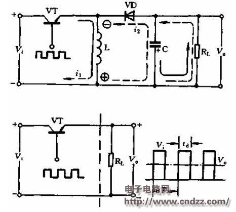
The operation of the inductor L, capacitor C and load RL in parallel is used in the figure below. When the switching tube VT is turned on, the diode VIII is reverse biased, and the input voltage vi only stores energy for the inductor L. At this time, the current on the load RL is discharged by the capacitor C which has been charged in the previous several cycles, and the current direction is as shown by the solid line in the figure. When the switching tube VT is turned off, the polarity of the self-induced electromotive force on the inductor L is upper and lower, and the inductor releases the stored magnetic energy f. The diode supplies energy to the capacitor C through the diode, and simultaneously supplies power to the load RL. Shown. These three components function the same as in a series switching power supply.
As shown in the figure below is the circuit diagram of the working principle of the parallel switching power supply.
Thermometer Manometer,Filled Pressure Gauge,Digital Oil Pressure Gauge,Electric Oil Pressure Gauge
ZHOUSHAN JIAERLING METER CO.,LTD , https://www.zsjrlmeter.com