
Abstract: The satellite measurement and control multi-beam system introduced in this article uses a new generation of TigerSHARC DSP chip and FPGA device recently launched by ADI to form a signal processing module, and uses DSP software programming to complete the calculation of direction finding and beam synthesis weights, and then use FPGA devices combine the original signals and weights into beams, and we use two igerSHARCDSP chips to complete the system design. The high-performance DSP chip ensures that the data can be processed accurately and in time, and also constitutes an important part of the system.
I. Introduction
The satellite measurement and control multi-beam system mainly implements measurement and control for satellite signals. It includes two aspects: signal direction of arrival (DOA) estimation and digital beam synthesis.
The direction of arrival estimation is the super-resolution estimation of the direction distribution of the spatial signal, and the parameters of the spatial source signal such as azimuth angle and elevation angle are extracted.
Digital beam synthesis is also called spatial filtering. It is mainly used to adaptively change the weighting factor of each array element according to the change of the signal environment to form the main beam in the direction of the desired signal and form a null in the direction of the interference signal to reduce the sidelobe level. It enhances the desired signal while suppressing useless interference and noise to the greatest extent, and extracts useful signal features and information contained in the signal. There are many algorithms for direction finding and beam synthesis. Choosing a suitable algorithm to meet the needs of the system is an important aspect. On the other hand, the system has certain requirements for real-time performance, requiring the calculation of direction finding and beam synthesis weights within a limited time.
Two, TigerSHARC DSP chip introduction
TigerSHARC101S is a high-performance fixed/floating-point DSP recently launched by AD company. It has extremely high processing power. It adopts a static superscalar structure. It has the large-capacity instruction buffer pool and instruction jump function of the superscalar processor, and The instruction-level parallel operation can be predicted by the compiler before the program is executed. Its main performance indicators are:
(1) The main frequency is 250 MHz, that is, the single instruction cycle is 4 ns; there are 2 equivalent processing units to support SIMD (single instruction multiple data) mode;
(2) There are 3 independent 128-bit data buses inside the system, which respectively access their respective 2 Mbit storage spaces;
(3) The external data bus of the system is 64 bits, the address bus is 32 bits, and the external addressing space is 4G words;
(4) Four 8-bit full-duplex link ports, each can work independently. In a multi-processor system, the link port can be used as a point-to-point communication between processors to form a distributed multi-processor system. 14 DMA channels, which can be used for background transfer;
(5) The scalability is strong, and the shared parallel bus can support 8 TS101S connected together for high-speed digital signal processing.
Due to the large amount of calculation for direction finding and beam synthesis algorithms, the system has requirements for signal processing time, and a single DSP cannot complete the task. This system makes full use of the parallel processing capabilities of the TS101S DSP chip and adopts a multi-processor parallel structure to complete signal processing. deal with.
Three, algorithm research
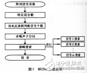
There are many algorithms for direction finding and beam synthesis, and various algorithms have their own advantages. Through the simulation and performance comparison of these algorithms, the MUSIC (Multiple Signal Characteristic) algorithm is finally selected to realize the direction finding, and the least square constant based on linear constraints is used. Modular algorithm performs beam synthesis. The basic principle of the MUSIC algorithm is to apply modern spectrum estimation theory and statistical theory and corresponding mathematics based on the sample data of the space incoming signal received by the elements at different positions in the antenna array, the antenna position parameters and the characteristic parameters of the elements. Calculate, estimate the spatial spectrum of the incoming wave, and analyze its energy distribution to determine the direction of the incoming wave in space, that is, detect the spatial source signal from the background noise and estimate the signal parameters such as azimuth, elevation, etc. This kind of direction finding technology has the function of fast, high sensitivity and high precision direction finding of multiple signals in the same channel at the same time in a strong interference environment. The algorithm is shown in flow chart 1.
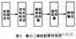
The least squares constant modulus algorithm based on linear constraints is an improvement of the least squares algorithm. It overcomes the interference capture problem of the least squares algorithm. The linear constraint method is used to optimize the initial weight vector to make it in the iterative process. It can quickly and accurately converge to the signal we expect, and is not affected by the signal power. The algorithm has fast convergence speed, the signal-to-interference and noise ratio of the output signal can be close to the ideal value, and it is not sensitive to the amplitude and phase difference. Through the algorithm simulation of the array signal, the performance of the least squares constant modulus algorithm can meet the system requirements. The flow of the algorithm is shown in Figure 2.
Four, DSP module design
1. DSP module function
The system uses a C size VXI standard chassis, and the slots include slot 0, DSP module and beam synthesis module. The DSP module is responsible for the calculation of direction finding and beam synthesis weights. The beam synthesis module performs beam synthesis on the original data and weights. The data exchange between the modules uses LBUS. The control terminal (microcomputer) sends commands to the DSP module through the VXI bus, and the DSP module responds to the received command in the form of external interrupt 2 and realizes the control of the system by the control interrupt. The command format is specified by the internal protocol.
According to the system requirements, the DSP module must complete the following 6 functions:
(1) Receive raw data and synthesized results
The data acquisition part is completed by the beam synthesis module. The DSP module timer receives the original data and the result data every 500 ms, and completes the calculation of direction finding and beam synthesis weights within 500 ms. The data exchange is carried out in accordance with the internal protocol established by the two modules.
(2) Automatic tracking
The initial or general state of the system is the automatic tracking state, the initial azimuth area of ​​the incoming wave has been given, and the DSP module measures direction every 500 ms to ensure that the system can follow the signal.
(3) Multiple direction finding
Taking into account the interference and errors in the actual signal, the average value of multiple directions is taken as the actual direction.
(4) Specify the direction of arrival
After specifying the direction of arrival, the weight of beam combining is directly calculated. At this time, the received original signal is not used but the signal is generated by itself to calculate the weight of beam combining.
(5) Display channel waveform or amplitude phase difference
The DSP board returns the amplitude and phase difference data to the control terminal and displays it on the terminal computer.
(6) Display the result of synthesis
The DSP module transmits the beam combining weight to the beam combining module, and the beam combining module combines the weight and the original data and then transmits it back and displays it on the control terminal.
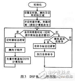
The block diagram of the DSP module is shown in Figure 3.
2. DSP module structure
The array antenna that receives the satellite signal is a 6×6 area array. The multi-channel receiver completes the signal sampling, and then after digital down-conversion, what is sent to the processing unit is 36 channels of I and Q, a total of 72 channels of data. Due to the large amount of data of the array signal and the complicated algorithm, we need to use two TS101S chips for parallel processing.
The interconnection structure of parallel system includes two ways: shared memory structure and distributed structure. The connection method of the shared memory structure is to connect all processors to one channel, which is generally a backplane bus (such as VXI bus), which can be used as a communication medium between processors or as a communication medium between processors. Data communication between shared memories. The data transmission bandwidth of this structure is far greater than that of directly connected communication ports, but there is a problem of bus competition. As the number of processors increases, the average bus bandwidth of the processors will decrease, which affects data throughput. The distributed structure processor carries on the direct data transmission through the link port, the link port provides high-bandwidth point-to-point communication between the processors. This kind of connection is entirely for communication between processors, but it will take up the internal resources of other DSP chips during data transmission.
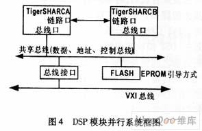
TigerSHARC DSP chip hardware can support these two parallel architectures at the same time. The former is realized by sharing the external address data control bus mode, and the latter is realized by the point-to-point interconnection of dedicated link ports between DSPs. From the perspective of the connection relationship of the communication network, the DSP module structure designed in this article is both a shared bus system and a distributed system. The external address bus, data bus, and control bus of the two DSP chips are directly connected, and they are connected together through a bus interface. To the VXI bus, realize data communication with other modules. Because there is 6 Mbit dual-port RAM inside each DSP, no external data memory is needed. The link ports of DSP A and DSP B are also directly connected, and the two DSPs can exchange data through the link*. The DSP module program is guided by EPROM, and the two DSPs share a 548K×8bit FLASH DSM2150 as the program memory. The block diagram of DSP module is shown as in Fig. 4.
The processing time of the entire DSP module is divided into three time periods, which are the time to read data from the buffer, the direction finding time, and the beam forming weight calculation time. The main overhead is the direction finding time. In order to make the DSP module have higher efficiency, tasks must be allocated reasonably according to the structure of the module and the performance of the Tiger DSP chip. Since the main overhead is the direction finding algorithm, it is especially important to solve the parallel algorithm for direction finding. In the MUSIC algorithm, after determining the number of signals, the peak search is performed on each signal area, and finally the signal direction is locked. The system can measure up to 4 signals from different directions. Therefore, the peak search area is divided and handed over to two The slice DSP searches at the same time, which can save a lot of time. The calculation of direction finding and beam synthesis weights cannot be performed at the same time. DSP A informs DSP B to perform beam synthesis and can return to read data from the buffer area. At this time, DSP B calculates the beam synthesis weights, which greatly improves Degree of parallelism. The command of the control terminal to the DSP module is read in through an external interrupt, and the timer clock is closed when the command of the control terminal is executed.
The program framework of the DSP module is constructed in C language, and assembly is inserted in C to improve the operation efficiency, and make full use of the SIMD structure of the TigerDSP chip dual processor core. In order to better optimize the entire program, use the development software Tool Linear profiling analyzes the proportion of time occupied by each sub-function, thereby optimizing the bottleneck of the program. Parallel system design and some optimization measures enable the running time of the DSP module to meet the requirements of system design.
3. Features of DSP module design
In the design of the DSP module of the satellite measurement and control multi-beam system, we have considered many factors, which can be summarized as the following characteristics:
First of all, the high-performance TigerSHARC DSP parallel structure guarantees the performance of the system. The system requires the determination of up to 4 directions of arrival and beam synthesis within 500 ms. Using two Tiger SHARC DSPs to work in parallel, it can be completed within 300 ms. Allows the system to have plenty of time to respond to commands from the control terminal.
Secondly, the superior performance of direction finding and beam synthesis algorithms ensure the stable operation of the system, and the accuracy of direction finding is guaranteed within 0.5°. After the signal is beam synthesized, the noise signal is suppressed, and the signal-to-noise ratio has been greatly improved. . In addition, tasks are distributed in parallel in the dual DSP processors, which improves the efficiency of program operation.
Third, the complete communication protocol between the DSP module and the beam synthesis module and between the external control terminal ensures the accurate transmission of data and commands. This communication protocol is customized according to actual needs, and has a certain fault tolerance function to ensure the normal operation of the interface between each module.
Finally, the design of the system control flow is reasonable. We use DSP's external interrupts 1, 2, timer interrupts, and vector interrupts for communication between the two DSPs to control the system. In order to enable the high-speed running DSP to effectively communicate with each other. Other modules and external control terminals communicate, and the design of the program flow has been carefully scrutinized to provide a guarantee for the stable operation of the DSP.
Five, concluding remarks
This article discusses the parallel implementation of algorithms in the DSP module of the satellite measurement and control multi-beam system and the allocation of parallel processing tasks. A series of measures have been taken to optimize the overall program of the DSP module, and the idea of ​​modularization has been applied. The structure is reasonable and can meet the needs of the system. demand.
Other household electric appliance
gree , https://www.greegroups.com