
Overview:
"We chose NI hardware and software development systems to reduce system development time, ensure system reliability, simplify the implementation of automated test solutions, and maintain and repair."
A high-voltage battery model, simulated high-voltage current sensor and temperature sensor, and simulated high-voltage battery faults create a hardware-in-the-loop system for quality diagnostics for the battery management system (BMS) ECU.
We use the HIL system to test our complex real-time systems. This technology provides a platform to effectively check the control state of test hosts that require dynamic models.
System Overview We use the BMS HIL system to test high voltage batteries for electric or hybrid vehicles to evaluate the control logic and fault diagnostics of the BMS. We created a battery model using Simulink and then applied the battery model to the development platform using the LabVIEW Simulation Interface Toolkit. We also use NI PXI systems to ensure efficient and reliable operation of the system.
The BMS HIL system enables quality diagnostics in a variety of test cases. By writing an automated test scenario, we reproduce all possible test cases for the battery system and use NI TestStand to organize and manage individual case scenarios.
We use LabVIEW to quickly deploy systems that use NI PXI to quickly generate and acquire signals that accurately reproduce battery pack voltage changes, including current and temperature changes in the BMS.
In addition, by using NI TestStand, we use BMS performance evaluation test cases to implement a simplified automated test solution.
Benefits of using NI products We chose the NI hardware and software development platform to reduce system development time, ensure system reliability, streamline the implementation of automated test solutions, and simplify system maintenance and repair processes. At the same time, NI products are also compatible with Simulink.
System hardware configuration
The BMS HIL system hardware includes a computer that installs LabVIEW and controls the entire system, a real-time NI PXI hardware platform that captures and provides signal output, a battery pack voltage generator that mimics the battery pack, and a set of signal conditioning units. In addition, the system includes a fault injection module that simulates various test errors, a power supply that supplies power to the BMS ECU, and an interface box that connects the HIL simulation system to the ECU.
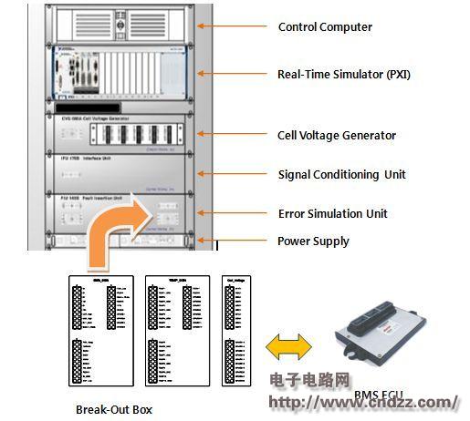
Figure 1: BMS HIL hardware-in-the-loop system hardware configuration (please read the PDF for details)
Vacuum Cleaner Bldc Dry Motor,Vacuum Cleaner Bldc Motor,Dry Bldc Motor For Vacuum Cleaner,Bldc Brushless Motor Vacuum Cleaner
Zhoushan Chenguang Electric Appliance Co., Ltd. , https://www.vacuum-cleaner-motors.com