
This article refers to the address: http://
introduction:
With the increasing complexity of automotive electronic systems, diagnostic functions have become an important part of ECU software design, and are critical to the normal operation of ECU control systems and the marketization process for large-scale applications. With the increase of ECU functions and the need for upgrading, diagnostic standards and vendor-defined diagnostic functions are becoming more and more abundant, and various service sub-functions are becoming more and more detailed, which increases the difficulty of diagnosis. Therefore, in-depth study of diagnostic protocols and Its implementation is very necessary. The K- line and CAN bus are two diagnostic standards widely used in the industry [ 1 ] . The CAN bus is widely used in European and American cars, and the K- line is widely used in domestically produced vehicles. The author has developed a BCM (Body Control) for a domestically produced vehicle. Module , body control module ) experience, analyze K- line specification, and then tell the design and implementation of BCM diagnosis function from two aspects of fault self-diagnosis and online diagnosis.
1 K line protocol analysis
K-line is defined by ISO9141 serial data bus for communication diagnostics, ISO 14230 on the basis of which the bus voltage ISO9141 extended to 24V, and a complete definition of the protocol KWP2000, improved communication and diagnostic criteria, diagnostic extended service [2] . The K- line communication adopts the SCI data format, the data link layer is implemented in software on the serial port communication, the physical layer is relatively simple, the half-duplex asynchronous communication is completed through a single physical line, and the physical level of the LIN bus physical layer chip can be completed. Conversion with logic levels.
ISO14230-1 defines the K- line physical layer protocol, ISO14230-2 defines the data link layer protocol, ISO14230-3 defines the application layer protocol and various diagnostic services, and the following three message structure, initialization process, timing parameters The aspect focuses on its data link layer protocol.
1.1 Message Structure
The structure of the K- line diagnostic message is shown in Table 1 :
Message header | Data field | Checksum | ||||
Fmt | Tgt | Src | Len | Sid | Data | CS |
Up to 4 bytes | Up to 63 bytes or 255 bytes | 1 byte | ||||
Table 1 K- line diagnostic message structure
Â
The K- line message consists of a message header, a data field, and a checksum. Format byte header comprises Fmt, the target address Tgt, the source Src and the additional address information length Len; data field includes a service identifier Sid and data Data, which is determined by the length and Len Fmt; single-byte checksum CS correction The calculation is performed by summing all the data in the header and data fields, ignoring the carry generated in the summation process.
1.2 initialization process
Before the diagnostic device performs any diagnostic service on the ECU , it first needs to establish diagnostic communication with the ECU , which is achieved through the "initialization process". ISO 14230 defines two initialization methods - 5 Baud initialization and fast initialization, 5 Baud initialization is for backward compatibility with ISO9141 , and now widely implemented is a fast initialization method. The process is shown in Figure 1. The diagnostic device sends a WuP (WakeUp Pattern) , then sends a StartCommunicationRequest , the ECU detects the WuP , and then sends a StartCommunicationResponse to return the message header format and timing parameters supported by the ECU .
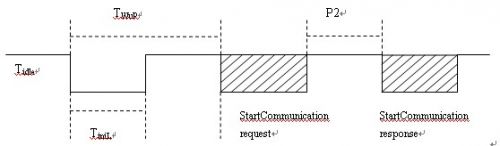
Figure 1 fast initialization process
1.3 timing parameters
In the diagnosis process, some timing parameters must be observed to ensure normal diagnostic communication. ISO14230 defines four timing parameters to manage inter-byte timing and inter-message timing. Figure 2 is a schematic diagram of timing parameters. Table 2 explains The meaning and value range of these four timing parameters.
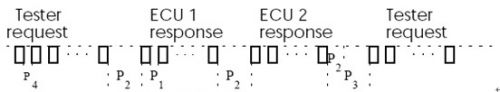
Figure 2 Schematic diagram of timing parameters
Â
Parameter variable | description | Minimum value (ms) | Maximum value (ms) |
P1 | Inter-byte time interval for ECU response | 0 | 20 |
P2 | End of the request and diagnostic ECU response interval which starts or ends and the next in response ECU ECU response time interval between the start | 25 | 50 |
P3 | Time interval between the end of the ECU response and the start of a new request from the diagnostic unit | 55 | 5000 |
P4 | Inter-byte time interval requested by the diagnostic | 5 | 20 |
Â
Table 2 timing parameters
2 diagnosis
Diagnosis refers to the continuous monitoring of the operation of each component during the operation of the electronic control system of the vehicle, fault location and storage, and then online reading through the diagnostic tool supporting the diagnostic protocol to obtain fault information, including self-diagnosis and online diagnosis. Two parts [ 3 ] .
2.1 self-diagnosis
Self-diagnosis refers to the process of real-time monitoring of the system, according to the operating state of the electronic control system reflected by the monitoring phenomenon, through further data analysis, to determine the location, type and cause of the fault, and to make corresponding adjustments to the system anomaly.
The main function of BCM is to control the load of door lock, window, lamp and wiper [ 4 ] . Correspondingly, the main fault of BCM is open load and short circuit. Open circuit faults do not have serious consequences, and can be implemented using the current mirroring function of the load driver chip. A certain sampling period is set, and the load working current is periodically sampled by the sampling resistor. If the operating current is less than a certain threshold and continues for a period of time, an open circuit fault is considered to occur.
When the short circuit occurs, the load operating current is very large, and the fault continues to cause quite serious consequences. During the experiment, it is found that the short-circuit fault of the lamp exceeds the order of ten milliseconds, and the power supply with relatively low power is pulled down to the ground. Causes all ECUs that take power from the car battery to reset, so short-circuit faults need to be detected in time and the relevant load is turned off.
Dynamic circuit.
Since there is a large surge current when the load starts, it needs to be distinguished from the load short circuit to avoid false positives. The inrush current duration is generally on the order of milliseconds. The sampling period for setting the load operating current is 10 milliseconds. If the two sampling operating currents exceed the threshold, the short-circuit fault is considered to occur. In practical applications, the 10ms sampling period will affect the system operating efficiency and increase the current consumption. If the sampling period is set too long, it may cause serious consequences of not detecting the short-circuit fault in time, in order to improve the system efficiency and real-time detection of short-circuit faults. Saturation, short-circuit fault detection can be achieved by monitoring the load drive voltage.
When the load driven by the high-side switching MOSFET is short-circuited to ground, the load driving voltage is 0 v . When the load driven by the low-side switching MOSFET is short-circuited to the power supply, the load driving voltage is the power supply voltage. The load driving voltage is divided and processed, and the processor IO pin that can trigger the interrupt is detected. The short circuit fault can trigger the IO pin interrupt, which can improve the real-time performance of the short circuit fault detection, and there is no misjudgment of the load starting load. Short circuit condition.
2.2 Online diagnosis
Online diagnosis refers to the process in which the diagnostic device sends a diagnostic service request according to an international or enterprise-defined diagnostic protocol, and the ECU returns a response according to the service request. It should be pointed out that with the increasing complexity of automotive systems and the increase in ECU functions, online diagnostics are no longer limited to early read fault codes, but also include software upgrades, version configurations, and more. The current internationally accepted diagnostic protocols including CAN bus based on the ISO15765 and ISO14230-based K-line [5].
The K- line based diagnostic network uses a bus network architecture. Multiple ECU nodes are connected together by a single K- line and a diagnostic instrument. Each ECU has a specific physical address and logical address. The diagnostic device passes the physical address or logical address to the ECU. For addressing, the topology is shown in Figure 3 :
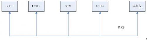
Figure 3 Diagnostic Network Topology
Â
The online diagnosis process is as follows: First, the diagnostic device establishes a “diagnostic communication†between the ECU and the specific address through the initialization process, automatically enters the “diagnostic session†of the default mode, and can also establish a specific mode of “diagnosis†through the SDS service (StartDiagnosticSession Service). Session", which determines which diagnostic services can be performed during this diagnostic session, and disconnects Diagnostic Communications via the StopCommunication Service after the diagnosis is complete. The diagnostic service is identified by the service identifier Sid in the K- line message structure described in Table 1. ISO14230-3 defines the Sid and Data of various diagnostic services. For example , the Sid of the ClearDiagnostic Information Service request is 0x14. Data is a two-byte identification code group (groupOfDTC) , 0xFFFF indicates all fault codes , 0x0000-0xFFFE is the OEM's custom fault code combination, and the service request, affirmative response, and no response should be defined as a table. 3 , Table 4 and Table 5 . Other diagnostic services are not described here.
Clear diagnostic information request | ||
parameter | Description | coding |
CLRDTC | The diagnostic information is cleared and this service allows the diagnostic information recorded by an ECU to be erased. | 0x14 |
groupOfDTC | DTC group | 0x0000-0xFFFE= Vendor-defined fault group 0xFFFF=The entire fault group |
Table 3 clears the diagnostic information request
Clear diagnostic information to respond positively | ||
parameter | Description | coding |
CLRDTCPR | Clear diagnostic information to respond positively | 0x54=0x14+0x40 |
groupOfDTC | DTC group | 0x0000-0xFFFE= Vendor-defined fault group 0xFFFF=The entire fault group |
Table 4 clears the diagnostic information and responds positively
Clear diagnostic information negative response | ||
parameter | Description | coding |
CLRDTCNR | Clear diagnostic information negative response | 0x7f |
CLRDTC | Clear diagnostic information request Sid | 0x14 |
RC | Response Code | 0x12= Unsupported subfunctions 0x22=The condition is incorrect 0x78= Respond to hang |
Table 5 clear diagnostic information negative response
Conclusion
With the development of automotive electronics, diagnostic functions have become an indispensable part of the development and design of ECUs . The ISO 1430 based on K- line is a very comprehensive set of on-board diagnostic protocol standards widely used in domestically produced vehicles. In this paper, a body control module BCM diagnostic functions designed to analyze the data link layer and application layer protocol specification K ray diagnosis, describes BCM achieve diagnosis based on the K-line, having a good reference.
Others Washing Machine Motor,Drain Motor Washing Machine,Washing Machine Dryer Motor,Inverter Motor Washing Machine
WUJIANG JINLONG ELECTRIC APPLIANCE CO., LTD , https://www.jinlongmotor.com