
Prof. Zhou Ligong's new book "Programming for AMetal Frameworks and Interfaces (Part 1)" introduces the AMetal framework in detail. By reading this book, you can learn highly multiplexed software design principles and development ideas for interface programming. Focus on your own "core domain", change your own programming thinking, and achieve common progress between the company and the individual. Authorized by Professor Zhou Ligong, from now on, the Zhiyuan Electronic Public Number will serialize the contents of the book, and is willing to share it.
The fifth chapter is to explain AMetal in depth . The content of this article is 5.2 LED digital tube interface.
5.2 LED digital tube interface
> > > 5.2.1 Static display
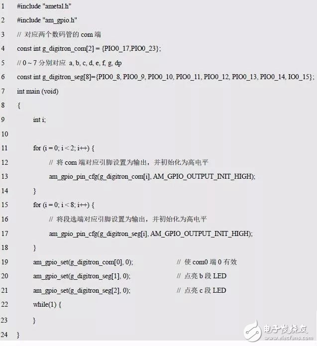
Take the LED digital tube circuit composed of two common anode LN3161BS shown in Figure 4.10 as an example. When the low level is output to the com0 terminal and the low level is output to the b and c segments at the same time, the LED is lit. The character "1", the corresponding code is detailed in Listing 5.22.
Listing 5.22 Digital Tube Static Display 1 Sample Program (1)
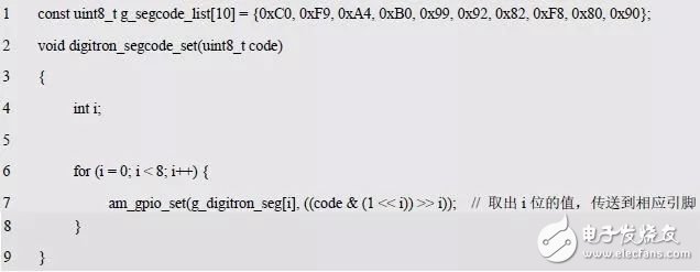
In order to facilitate access, you can store the segment code in an array. The segment code transfer function is shown in Listing 5.23.
Listing 5.23 Segment Transfer Function
If you want to output the number 3, you can use the following code to achieve:

If you still need to add a decimal point? The 0x7F on "and" clears the highest bit. which is:

What if you want to output a number that is not in the segment code table? Then directly pass the corresponding segment code. which is:

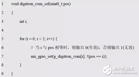
So what about the digital tube display? This is the bit code transfer problem, the corresponding function is detailed in Listing 5.24.
Listing 5.24 Bit Code Transfer Function
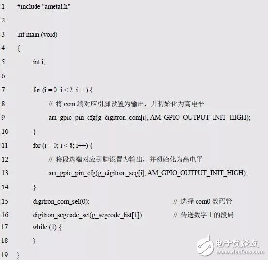
With the segment code and bit code transfer function, it is very simple to display the number 1 at com0, as shown in Listing 5.25.
Listing 5.25 Digital Tube Static Display Number 1 Sample Program (2)
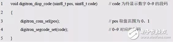
Obviously, by combining the above two functions, the segment code and bit code information can be transmitted at the same time. See Listing 5.26 for details.
Listing 5.26 digitron_disp_code() shows the function
Here, the main purpose is to display numbers. In order to avoid obtaining the segment code of the corresponding number from the segment code table every time, you can write a function for displaying the specified number at the specified position. See Listing 5.27 for details.
Listing 5.27 digitron_disp_num() shows the function
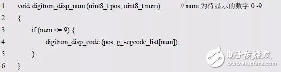
Since only the display of 0~9 is supported, it is necessary to perform judgment processing, that is, when the num value is less than or equal to 9, the display operation is performed. Why not judge the judgment greater than or equal to 0? Since the type of num is unsigned, it must be greater than or equal to 0. Obviously, an initialization function is required, so the initialization of these pins is all placed in Listing 5.28.
Listing 5.28 Digital Tube Board Level Initialization Function

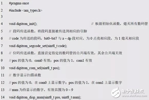
At this point, the programming is completed, and the relevant function interface is declared to digitron0.h. See Listing 5.29 for details. When you need to call later, you only need #include "digitron0.h".
Listing 5.29 digitron0.h file contents
> > > 5.2.2 Dynamic display
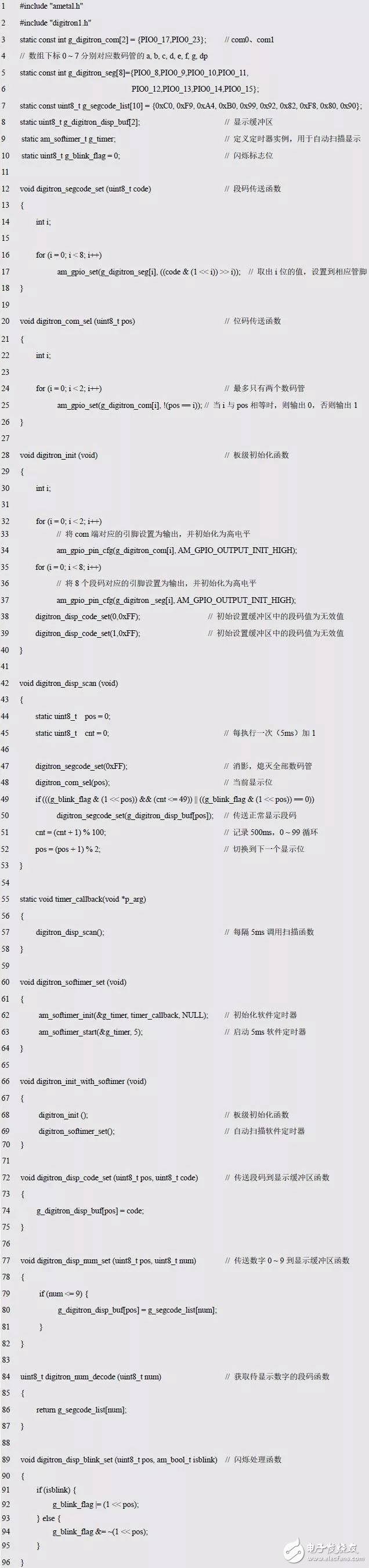
As shown in Listing 5.30, the digitron1.h interface that you have mastered before, the corresponding implementation code is shown in Listing 5.31.
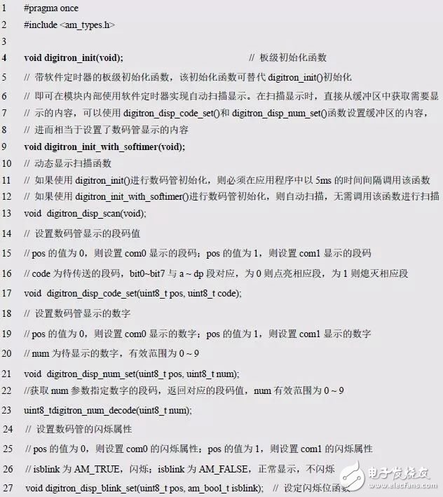
Listing 5.30 digitron1.h file contents
Listing 5.31 digits of the digitron1.c file
> > > 5.2.3 Code Refactoring
Refactoring is the way to improve the quality of the code, ie the way to optimize the internal structure without changing the external interface. When refactoring, you must prioritize the unit test code to ensure that the refactoring does not break the original functionality. The external interface in C language usually refers to the content of the header file, that is, the data structure, function, macro signature (name and order of the name, parameter and return value), the definition and behavior of the constant, which are necessary when externally calling the code we write. Wait. The definitions of macros and structures in static functions and .c files are not external interfaces. The caller does not need to modify any code as long as the external interface has not changed. If the caller and the creator belong to the same department, there is no need to stick to the form to prohibit modification of the external interface.
Because people are accustomed to use 1 to light the LED, 0 means to extinguish the LED, so whether the digital tube is a common cathode or a common anode, the design of the segment code table should conform to people's daily habits, which will be corresponding to the "segment code table". The data is set to 1 to indicate that the corresponding segment is lit. If 1 is used to indicate the lighting of the LED, this is exactly the segment code of the common cathode digital tube. If it is a common anode digital tube, directly use "~" to invert the segment code, so the segment code table is unified.
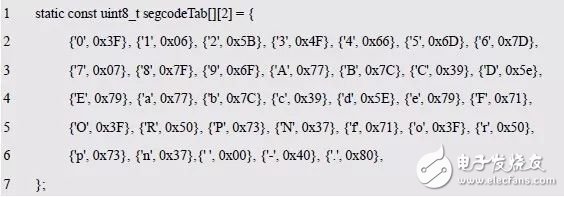
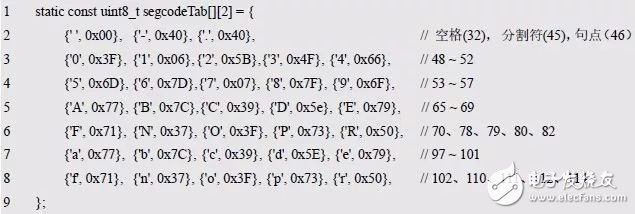
The next step is to design the segment table. The current idea is .-ABCDEFabcdefORPNorpn, except for O and o, the case is the same. Since the character and the segment code are both expressed in one byte, in order to save the character information and the corresponding segment code information, the displayed character and the segment code value can be combined to form a two-dimensional array, and the corresponding segment code table is established. See Listing 5.32 for details.
Listing 5.32 Character Segment Table
The interface function for accessing the segment table is detailed in Listing 5.33.
Listing 5.33 Segment Access Interface Function
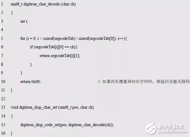
In the decoding function digitron_char_decode(), a for loop is used to traverse the segment code array. When the corresponding character is found, the segment code corresponding to the character is returned. Obviously this decoding method is simple and easy to understand, but it is inefficient.
Since characters are essentially an integer, you can compare sizes. If the segment code table is arranged in order according to the character size, you can use the binary method to perform fast search, that is, compare the character to be searched with the middle character of the search range each time: if it is smaller than the middle character, the search range is reduced to half. The lower half, then continue to search; if it is greater than the middle character, the search range is reduced to half of the upper half, and then continue to search; if they are exactly equal, the corresponding character is found.
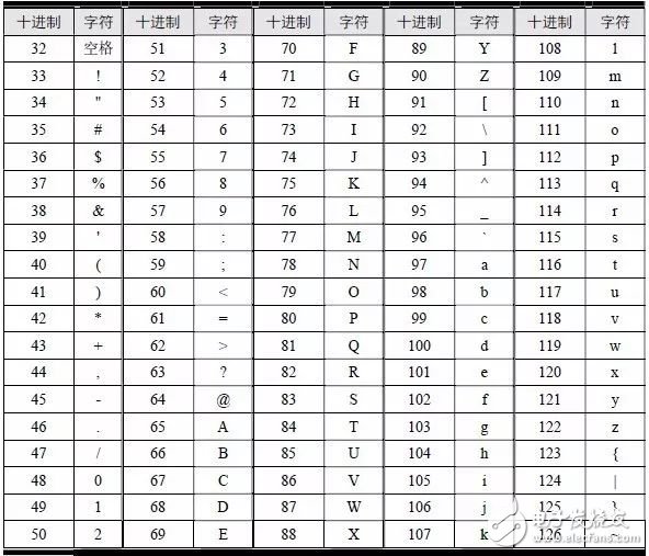
In order to use the dichotomy to search, the code break table needs to be arranged in order according to the size of the characters. This requires knowing the integer values ​​corresponding to the characters in the segment code table. These values ​​can be obtained by querying the ASCII code table. See Table 5.7. Only the displayable characters (32 ~ 126) are listed in the table. There are 95 characters in total. Other non-displayable characters (0 ~ 31 and 127) are not displayed in the table because they cannot be displayed.
Table 5.7 ASCII Table (95 displayable characters)
The segment code table can be redefined based on the corresponding integer value of each character in the ASCII code table. See Listing 5.34 for details.
Listing 5.34 Character Segment Code Table (ascending order)
After the segment code is arranged in order, you can use the binary search. The implementation of updating the decoding function is shown in Listing 5.35.
Listing 5.35 Decoding function based on binary search

It can be seen that the code implemented by the dichotomy is slightly more complicated than the sequential traversal lookup method. When the scope of the search is small, such as only 33 search terms in the segment code table, the efficiency advantage of the binary method is not obvious. Is there a better way?
When defining the segment table in the previous section, the two-dimensional array is used to store the characters and the corresponding segment code into the array. One character occupies 2 bytes of storage space, occupying a total of 66 bytes of space.
The ASCII code table has 95 display characters, and the corresponding decimal number ranges from 32 to 126. If the segment code table is created from the first displayable character, and the segment codes of all displayable characters are sequentially arranged into an array in the order of characters, the index of the array contains character information, for example, element 0 It represents the corresponding character of 32, that is, the space, and the element of No. 1 represents the character corresponding to 33, that is, '!'... In this way, since the index has a one-to-one correspondence with the character, the corresponding character information can be obtained through the index. Therefore, in the segment code table, it is only necessary to use a one-dimensional array to store the segment code corresponding to each character. At this time, when decoding a character, directly convert the character into an array index, and then take out the corresponding segment code, without any search process. The sample program is shown in Listing 5.36.
Listing 5.36 uses a one-dimensional array to store segment code (1)
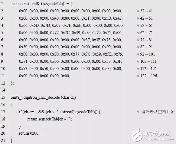
It can be seen that this method makes the time efficiency of segment code search optimal. In the segment code table, since many ASCII code digital tubes cannot be displayed, in order to ensure the correspondence between indexes and characters, 0x00 must also be used to indicate the corresponding segment code. This causes a waste of space to a certain extent. The coded array corresponding to 95 characters occupies 95 bytes of storage space, which is 29 bytes more than the two-dimensional array.
Observing the definition of the segment code array, we can find that there is a large segment of 0x00 at the beginning and the end (starting with 13 consecutive 0x00 and ending with 12 consecutive 0x00). For this reason, when defining the segment code array, you can not Space as the starting character, the first segment code is not 0x00 characters ('-', decimal is 45, segment code is 0x40) as the starting character of the segment code, and at the same time, the consecutive 0x00 at the end of the segment code table is removed. To save memory space, see Listing 5.37.
Listing 5.37 uses a one-dimensional array to store segment codes (2)
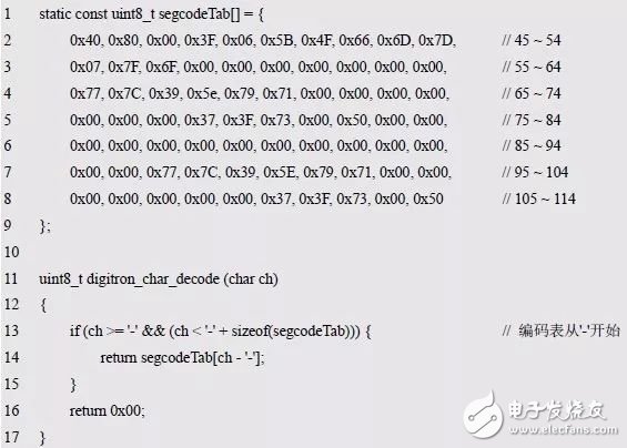
At this point, the entire one-dimensional array takes up 70 bytes, which is only 4 bytes more than the two-dimensional array. Although it takes up to 4 bytes of storage space, the efficiency improvement is very obvious.
Since the segment code or character is used directly, when the number 3 is displayed, the number 3 cannot be directly written as before, but the character 3 should be written. such as:

For example, to display a custom segment code, program it in the following way:

For example, if '3.' is displayed, it is programmed in the following way:

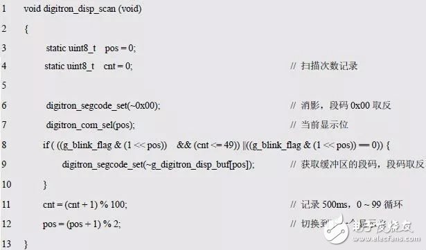
Since the segment code uses 1 for the LED segment, in practice, the MiniPort-View uses the common anode digital tube. Therefore, the segment code needs to be inverted and the igitron_disp_scan() function is further modified. See Listing 5.38 for details. .
Listing 5.38 Dynamic Scan Display Function
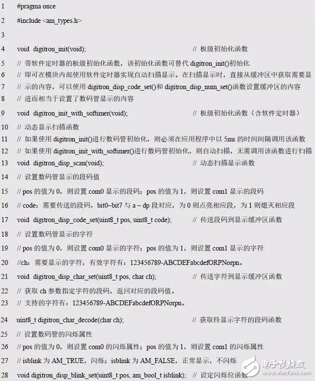
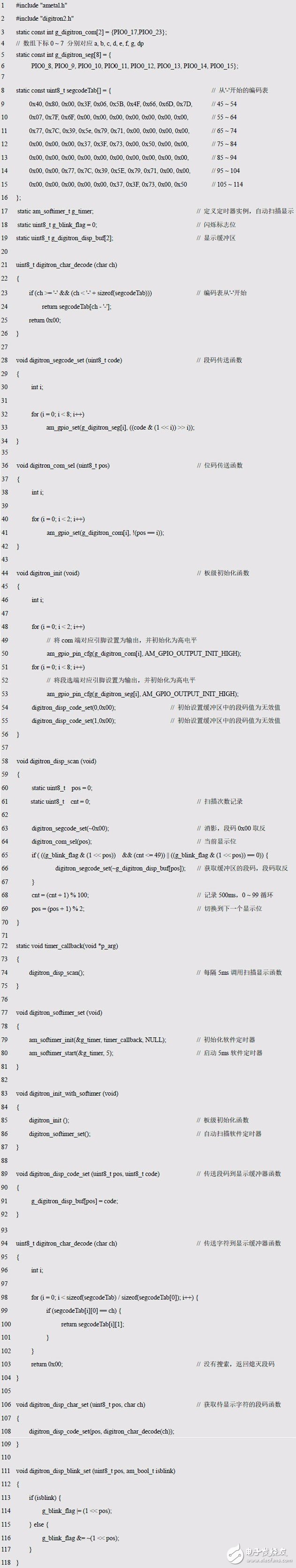
Finally, declare all of these interfaces to the digitron2.h file shown in Listing 5.39. The relevant code is all placed in the digitron2.c file shown in Listing 5.40.
Listing 5.39 digitron2.h file contents
Listing 5.40 digitron2.c file contents
Using the interface function in digitron2.h, you can also implement a counter from 0 to 59 seconds. The code is shown in Listing 5.41.
Program Listing 5.41 0~59 Second Counter Sample Program (4)
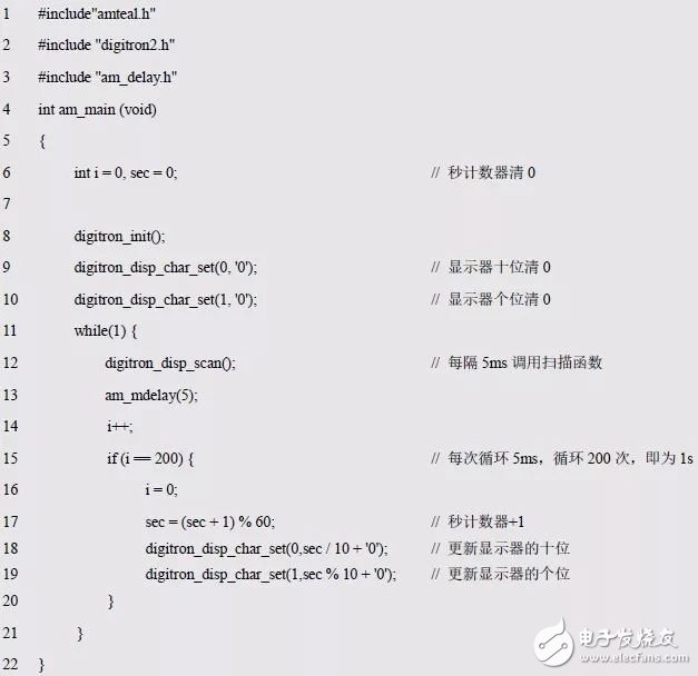
The purpose of Listing 5.41 (17~18) plus '0' is to change the number to a character.
Small computer system interface (SCSI) is an independent processor standard for system level interfaces between computers and intelligent devices (hard disks, floppy drives, optical drives, printers, scanners, etc.). SCSI is an intelligent universal interface standard.
The maximum synchronous transmission rate of the original SCSI standard was 5MB / S (scsi-1, also known as narrowscsi, in 1986, the maximum support for seven devices, the clock frequency was 5MHz), and the later SCSI II specified two options for increasing the speed. One is to increase the frequency of data transmission, namely fast SCSI (in 1994, the maximum support for 7 devices) is 10 Mb / S (10 MHz) because the frequency is doubled; the other is to double the transmission frequency and increase the width of the data path from 8 bits to 16 bits. The maximum synchronous transmission speed of widescsi is 20MB / S (the clock frequency is 10MHz, in 1996, the maximum support for 15 devices).
The third generation of SCSI appeared around 1995, but there was no unified standard
1. Ultra SCSI with maximum synchronous transmission speed of 20MB / S (also known as FAST-20 SCSI, clock frequency of 20MHz);
2. Ultra wide SCSI with maximum synchronous transmission speed of 40MB / S (same as 1);
3. Ultra2 SCSI with maximum synchronous transmission speed of 40MB / S (also known as fast-40 SCSI, clock frequency of 40MHz, 1997).
Later, some newer SCSI standards appeared
1. Ultra2 widescsi with maxmum synchronous transmission speed of 80mb / S (clock frequency of 40MHz);
2. Ultra 3 SCSI with maximum synchronous transmission speed of 160MB / S (also known as ultra-160 or fast-80 wide SCSI, clock frequency of 40MHz plus double data rate, 1999);
3. Ultra 320 SCSI with maximum synchronous transmission speed of 320mb / S (also known as ultra 4 SCSI, clock frequency of 80MHz plus double data rate, 2002); 4. Ultra 640 SCSI with maximum synchronous transmission speed of 640MB / S (clock frequency of 160MHz plus double data rate, 2003, is the latest SCSI standard)
This interface is a convenient interface standard for system integration, cost reduction and efficiency improvement. More and more devices will use the SCSI interface standard. Therefore, there are many hard disks and SCSI CD-ROM drives with SCSI interface. However, due to the cost problem, they are mainly used on medium and high-end servers and workstations.
Metal Male SCSI Cover Section
ShenZhen Antenk Electronics Co,Ltd , https://www.atkconnectors.com