
Adjustable capacitor Murata genuine original
TZC3Z060A110R00 MURATA Murata adjustable capacitor original spot
Circuit Operation Principle The infrared remote control dimming and governor circuit consists of a power supply circuit, an infrared remote control circuit, a touch control circuit and a control execution circuit, as shown in Figure 3-158.
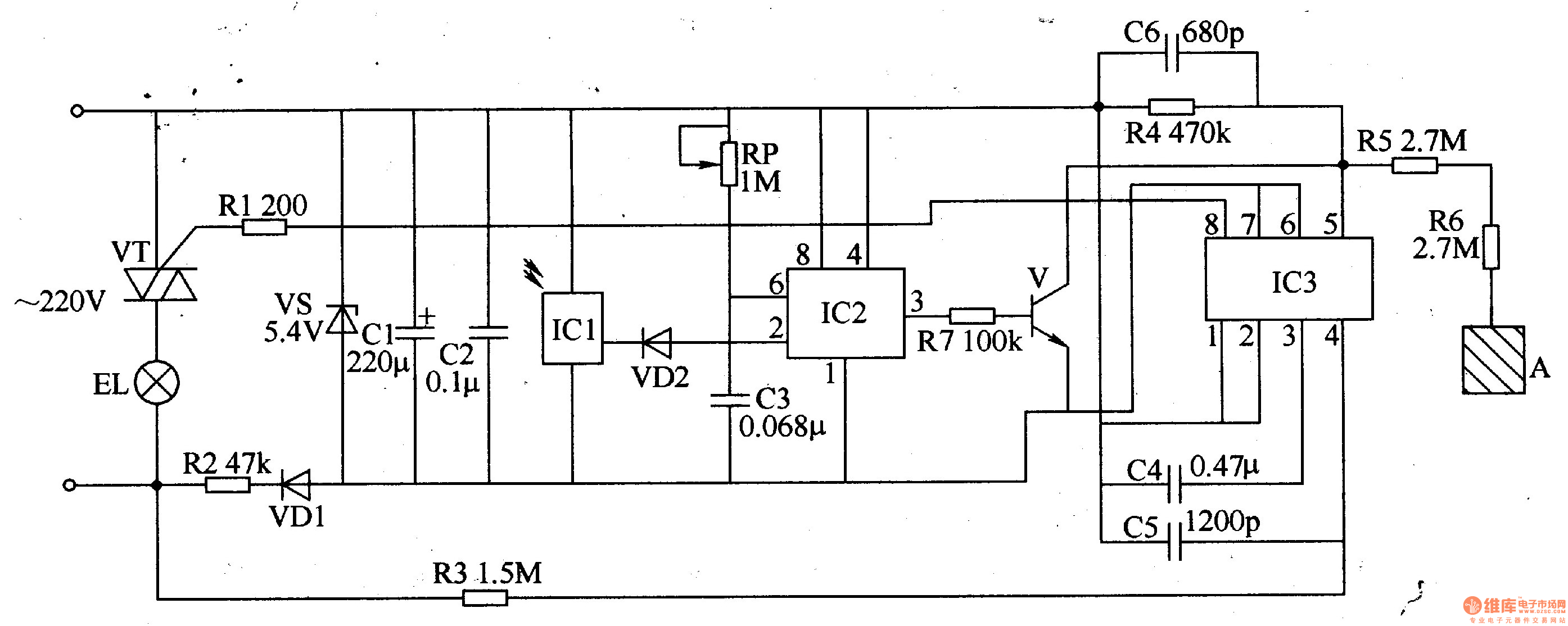
The power circuit is composed of a current limiting/step-down resistor R2, a rectifier diode VDl, a Zener diode VS, and filter capacitors Cl and C2.
The infrared remote control circuit is composed of an infrared receiving head ICl, a diode VD2, a time base integrated circuit IC2, a transistor V, a potentiometer RP, a capacitor C3 and a resistor R7.
The touch control circuit is composed of a touch dimming integrated circuit 1C3, a resistor R4-R6, a capacitor C4-C6, and a touch electrode sheet A.
The control execution circuit is composed of an IC3 internal circuit, a resistor R1, and a thyristor VT.
After the AC 220V voltage is derated by R2, VDl rectification, VS voltage regulation and Cl and C2 filtering, the DC voltage (Vcc) of about 5V is provided for ICl-IC3.
When the remote control button is pressed, the remote controller emits an infrared remote control pulse train (when the time of pressing the remote control button is less than 0·45, the remote controller outputs 1-3 pulses; if the time of pressing the remote control button exceeds 0.45, Then the remote controller outputs more than three bursts. 1C1 will receive the infrared pulse train for amplification, demodulation and shaping, and then output a low-level pulse to make VD2 turn on and C3 discharge quickly. When the voltage across C3 is lower than Vcc/3, the 3 pin of IC2 outputs a high level, which turns V on. When a pulse train passes, VD2 is turned off, +5V voltage is charged to C3 via RP, so that the voltage of pin 2 and pin 6 of IC2 keeps rising. When the voltage rises to 2Vcc/3, the circuit in lC2 flips and the 3 pin becomes Low level, V cutoff. If I1 outputs a low-level pulse again during C3 charging, C3 will discharge again, and IC3's 3 pin will keep output high.
When the electrode pad A is touched by hand for a short time (less than 0.4 s) or when the remote control button is clicked, the 8 pin of the lC3 will output a control pulse to turn the VT on or off, thereby causing the load (light or electric fan motor) to work. The power is turned on or off. When the electrode pad A is touched by hand for a long time (greater than 0.4s) or when the remote control button is pressed for a long time, the 8th pin of the IC3 will output a control pulse train to change the conduction angle of the VT, thereby adjusting the magnitude of the load power and realizing the illumination lamp. Stepless dimming or speed regulation of electric fans.
Adjust the resistance of the RP to change the sensitivity of the remote control.
Component selection
Rl and R3-R7 use 1/4W carbon film resistor or metal film resistor, R2 selects 1/2W metal film resistor.
RP uses WSW type organic solid variable resistor.
Cl uses aluminum electrolytic capacitors with a withstand voltage of 25V; C2-C4 uses monolithic capacitors; C5 and C6 use high-frequency ceramic capacitors.
VDl selects 1N4007 silicon rectifier diode for use. VD2 selects 1N4148 type silicon switch diode for use.
VS selects 1/2W or lW, 5.lV type silicon steady voltage diode.
V selects S9014 or 3DG9014 type silicon NPN transistor.
VT selects TLC336A (3A, 600V) type bidirectional thyristor.
ICl selects SFH506-38 or RPM-638 type integrated infrared receiving head; IC2 selects NE555 type time base integrated circuit; IC3 selects C57232 or 5M7232 type dimming control ASIC.
A can be made using thin copper sheets.
SHENZHEN CHONDEKUAI TECHNOLOGY CO.LTD , https://www.szfourinone.com