
As the signal travels along the transmission line, it will experience a transient impedance every moment. This impedance may be the transmission line itself, or it may be halfway or other components at the end. For the signal, it does not distinguish what it is. Only the impedance is felt by the signal. If the signal's perceived impedance is constant, then it will normally propagate forward. As long as the perceived impedance changes, the signal will be reflected. These factors may include excessively long traces, end-matched transmission lines, excessive capacitance or inductance, and impedance mismatch.
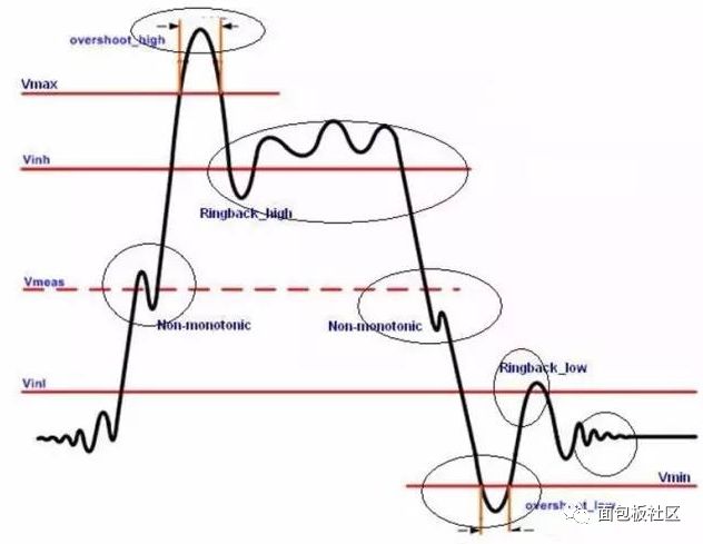
Reflections can cause signal overshoot, undershoot undershoot, ringing ringing, and sluggish edge, which is the staircase voltage wave. Overshoot is an underdamped state of ringing, and edge lag is an overdamped state of ringing. When the first peak of the signal exceeds the originally set maximum value. Overshoot is the first peak or valley of a signal transition. It is an additional voltage effect above the power level or below the reference ground level.
With the slowness of the edge, we have also become a step, backtracking, and its danger is mainly caused by false triggers.
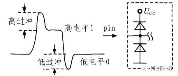
Undershoot refers to the next valley or peak of the signal transition. Overshoot and undershoot are both detrimental factors. Excessive overshoot voltages often cause long-term shocks that can damage the device, as shown in the figure above. A severe undershoot can exceed the threshold of the receiving device and cause a circuit logic error.
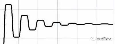
If the signal is reflected multiple times back and forth between the driver and the receiver, ringing occurs, which increases the time required for the signal to stabilize, and thus also affects the system's stable timing.
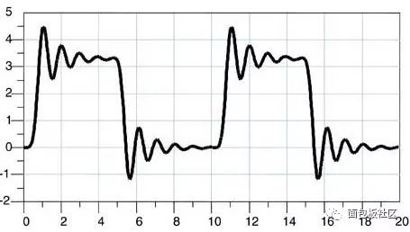
The details are as shown below
Circuit Design Tips:
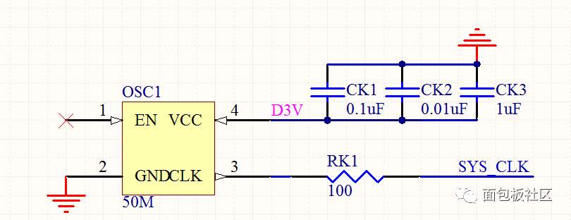
Generally, in the circuit design, if the clock signal link is relatively long, a small resistor, such as 22 ohms or 33 ohms, is serially connected to the clock output signal.
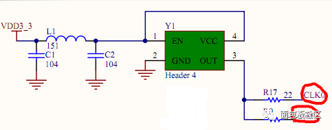
As for why, many mature designs do this, and it is an empirical design method. In fact, in fact, the role of this small resistor is to solve the problem of signal reflection. And as the resistance increases, the ringing will disappear, but you will find that the rising edge of the signal is no longer steep, and the series resistance is to reduce the reflected wave, to avoid overshoot caused by the superposition of the reflected wave. This solution is called impedance matching. We must pay attention to impedance matching. Impedance occupies an extremely important position in signal integrity problems.
Pure sine ware output
Optional MPPT/PWM solar charge controller 60A
MPPT Efficiency max 98%
DC Start & Automatic Self-Diagnostic Function

On/Off Grid Solar Inverter,Hybrid Inverter With Mppt Charge,pure sine wave solar inverter
suzhou whaylan new energy technology co., ltd , https://www.whaylan.com