
Plc communication includes communication between PLCs and communication between PLCs and other smart devices. With the development of computer control technology, the factory automation network has developed rapidly. Each PLC manufacturer attaches great importance to the communication functions of PLC and has launched their own network systems. The newly produced PLCs all have communication interfaces, and communication is very convenient. This chapter describes the design process of LabVIEW and Yonghong PLC communication. 11.1.1 Communication Hardware Connection Figure 11-1 shows the hardware diagram of Yonghong PLC. The hardware communication board can be selected. Figure 11-2 shows the communication interface of RS485 and RS232. 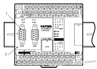 1. FBS-CB22 communication board (Communication Board referred to as CB) 2. FBS-CB22 communication board corresponding cover (each communication board has its corresponding cover) Figure 11-1 Yonghong FBS series PLC hardware
 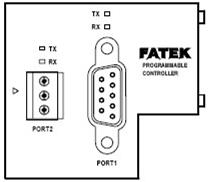 Figure 11-2 FBS-CB22 RS232 and RS485 interface communication board 11.1.2 PLC serial communication principle PLC standard host has built-in standard configuration of two communication interfaces, namely one RS232 and one RS485 communication interface, its RS232 interface is mainly used for The download program is used to communicate with the host computer and the touch screen, and the RS485 interface is mainly used to set up a network using the RS485 protocol to implement communication control. 1. RS232 interface RS232-C interface connector generally uses the model 9 DB-9 9-pin connector, only need 3 interface lines, that is, "send data", "receive data" and "signal ground" to transmit data, 9 The definition of each pin is shown in Figure 11-3.
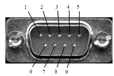
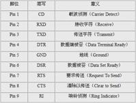 Figure 11-3 RS232-C interface connector is defined in the RS232 specification. The voltage value is +3V~+15V (usually +6V) is called "0" or "ON". The voltage is -3V~-15V (usually -6V) is called "1" or "OFF"; the RS232 "high potential" on the computer is about 9V, and the "low potential" is about -9V. RS232 is a full-duplex mode of operation. The voltage of the signal is obtained by reference to the ground. It can transmit and receive data at the same time. In the practical application, the RS232 interface is adopted, and the transmission distance of the signal can reach 15m. However, RS232 only has a single station function, that is, one-to-one communication. 2. RS485 interface RS485 uses two positive and negative signal lines as transmission lines. The voltage difference between the two lines is +2V~6V, indicating logic "1": the voltage difference between the two lines is -2V~6V, indicating logic "0". RS485 is a half-duplex working mode, and its signal is obtained by subtracting the signal levels of the positive and negative lines. It is a differential input mode, which has strong anti-common-mode interference capability, that is, good anti-noise interference; in practical applications, its transmission distance is up to 1200 meters. RS485 has multi-station capability, that is, one-to-many master-slave communication. In serial communication, data is usually transmitted between two stations. According to the transmission direction of data on the communication line, it can be divided into three basic transmission modes: simplex, half-duplex and full-duplex, as shown in Fig. 11. -4 is shown.
  Figure 11-4 Simplex, Half-Duplex, and Full-Duplex Communication Simplex communication uses a single conductor, and the transmitter and receiver of the signal have a clear directionality. In other words, communication takes place only in one direction. If the same transmission line is used as both the receiving line and the transmitting line, although the data can be transmitted in both directions, the communication parties cannot simultaneously transmit and receive data. Such a transmission method is called half duplex. When the half-duplex mode is adopted, the transmitter and the receiver at each end of the communication system are time-divisionally transferred to the communication line through the transceiver switch to perform direction switching. When data is transmitted and received, which are transmitted by two different transmission lines, both communication parties can perform transmission and reception operations at the same time. This transmission mode is full duplex. In the full-duplex mode, the transmitter and the receiver are provided at each end of the communication system, so that data can be controlled to be transmitted in both directions simultaneously. The full-duplex mode does not require direction switching. Serial communication can be divided into two types, one is synchronous communication and the other is asynchronous communication. When using synchronous communication, all characters are grouped into one group, so that characters can be transmitted one by one, but synchronization characters are added at the beginning of each group of information, and when there is no information to be transmitted, a null character is filled because of synchronous transmission. No gaps are allowed. When asynchronous communication is used, the transmission interval between two characters is arbitrary, so some data bits are used as separator bits before and after each character. In comparison, when the transmission rate is the same, the information in the synchronous communication mode is more efficient than the asynchronous mode because the proportion of the non-data information in the synchronous mode is relatively small. However, on the other hand, the synchronous mode requires that both parties transmitting information must coordinate with the same clock. It is this clock that determines the position of each information bit in the synchronous serial transmission process. In this way, if the synchronization method is adopted, the clock signal must be transmitted while the data is being transmitted. In the asynchronous mode, the clock frequency of the receiver and the clock frequency of the sender do not have to be exactly the same, but as long as they are similar, that is, they do not exceed a certain allowable range. In data transmission, asynchronous communication is widely used. The standard data format of asynchronous communication is shown in Figure 11-5.
  Figure 11-5 Asynchronous communication data format As can be seen from the format listed in Figure 11-5, asynchronous communication is characterized by one character and one character transmission, and each character transmission always starts with a start bit and ends with a stop bit. There is no fixed time interval between characters. Each time there is a start bit, followed by 5~8 data bits, followed by a check bit, which can be an odd test, or even parity, or no, and finally 1 bit, or 1 bit. Half, or a 2-bit stop bit, followed by a stop bit of indefinite length. Both the stop bit and the idle bit are specified as high, which ensures that there must be a falling edge at the beginning of the start bit to indicate the start of data transfer. 11.1.3 Yonghong PLC communication protocol Yonghong communication protocol can be realized simply through the serial port. The specific parameters of the host computer are shown in Figure 11-6. In addition to its own Yonghong standard communication protocol, Yonghong PLC also supports Modbus communication protocol (except Porto). The specific communication steps are as follows:
 Figure 11-8 VISA structure hierarchy Figure 11-9 VISA instrument control flow
 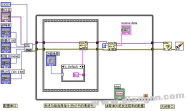 Figure 11-10 Serial Port Read and Write Program 11.1.5 Program Writing The panel of the PC and PLC serial communication program based on LabVIEW is shown in Figure 11-11. According to the communication protocol and data operation flow of Yonghong PLC, the program adopts the sequence structure. The sequential structure can realize the sequential flow of the data stream. First, open the serial port and set the serial port parameters (as shown in Figure 11-12). The baud rate is 9600 Bps, the serial port number is COM1, the even parity (Even), and the 7-bit data bit. The data stop bit is 10 (as shown in Figure 11-13).
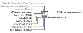 Figure 11-11 Program panel Figure 11-12 VISA serial port configuration
  Figure 11-13 Open serial port and set serial port parameter second step write command. First judge the command to see if it is legal. The rear panel program is shown in Figure 11-14. Then, determine whether the written command is too long, and combine the legal data into a writable command. The rear panel program is shown in Figure 11-15.
 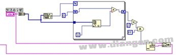 Figure 11-14 Checking the legality of the input command
 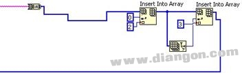 Figure 11-15. The data combination serial port write process takes time according to the communication protocol. Therefore, after this step, the delay is 250ms, as shown in Figure 11-16. The next step is to read the serial port return value. The returned value is read by VISA (as shown in Figure 11-17), and then analyzed and checked to determine if the received data is correct.
 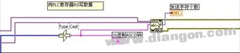 Figure 11-16 After the data is written to the R0 register of the PLC to verify the data, the operation flow is finished, and the VISA serial port can be closed (as shown in Figure 11-18).
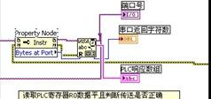
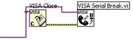 Figure 11-17 Read serial port return value Figure 11-18 Close serial port 11.1.6 Example summary This example uses the LabVIEW driver configuration method to establish a program for communication between the host computer and Yonghong PLC through VISA. For other brands and models of PLC communication, the same This method can be used. Similarly, inter-device communication for the Modbus protocol can also use such methods.
 Capacitor for Electric Furnace
Capacitor For Electric Furnace, commonly referred to as capacitors, are capacitors, expressed in the letter C.Definition 1: a capacitor, as the name implies, is a "charging vessel", a device that holds charge.Capacitor.Capacitors are one of the most widely used electronic components in electronic equipment. They are widely used in the fields of interleaving, coupling, bypass, filtering, tuning circuit, energy conversion and control.Definition 2: a capacitor consisting of any two conductors (including wires) that are insulated from each other and are very close together.
Electronic Components Capacitors,High Voltage Capacitors,Low Frequency Capacitor,Water Pump Capacitor,Capacitor for Electric Furnace
YANGZHOU POSITIONING TECH CO., LTD. , https://www.cnfudatech.com