
The keyboard structure of the matrix structure is more complicated. The column line is connected to the positive power supply through the resistor, and the I/O port of the MCU connected to the line line is used as the output end, and the I/O port connected to the column line is used as the input. Thus, when the button is not pressed, all inputs are high, indicating no key press. The line output is low. Once the button is pressed, the input line is pulled low. Thus, by reading the status of the input line, it is known whether a key has been pressed.
In a matrix keyboard , each horizontal line and vertical line are not directly connected at the intersection, but are connected by a button. In this way, a port (such as the P1 port) can constitute 4*4=16 buttons, which is twice as large as the port line is directly used for the keyboard, and the more the number of lines, the more obvious the difference, for example, adding another line. It can form a 20-key keyboard, and the port line can only use one more button (9-key). It can be seen that when the number of keys required is relatively large, it is reasonable to use the matrix method to make the keyboard.
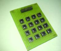
<1> Determining which key on the matrix keyboard is pressed introduces a "line scan method".
The line scan method is also called the line-by-row (or column) scan query method. It is the most commonly used method for key recognition. The keyboard shown in the above figure is introduced as follows.
1. Determine whether there is a key in the keyboard. Press all the line lines Y0-Y3 to low level, and then check the status of the column lines. As long as the level of one column is low, it means that there are keys pressed in the keyboard, and the closed keys are among the four keys that cross the low level line and the four line lines. If all the column lines are high, no key is pressed in the keyboard.
2. Determine the position of the closed key. After confirming that the key is pressed, you can enter the process of determining the specific close key. The method is: sequentially setting the row line to a low level, that is, when a certain row line is low, the other lines are high. After determining that a certain row line position is low, the level state of each column line is detected line by line. If a column is low, the button at the intersection of the column line and the line line that is set low is the closed button.
<2> Determining which key on the matrix keyboard is pressed introduces a "high and low level flip method".
First, let the P1 port be four high and the lower four bits be 0. If there is a button press, one of the upper four digits will be flipped to 0, and the lower four digits will not change. At this point, the row position of the pressed key can be determined.
Then let the P1 port be four digits high and the lower four digits. If there is a button press, one of the lower four digits will be flipped to 0, and the upper four digits will not change. At this point, the column position of the pressed key can be determined.
Finally, the two are ORed to determine the position of the pressed key.
For more information on matrix keyboards, please visit http://
Inverter With Charge Controller
Inverter with a charge controller is a device that combines the functionalities of an inverter and a charge controller into a single unit. This integrated system is commonly used in off-grid solar power systems to convert the DC (direct current) electricity generated by the solar panels into AC (alternating current) electricity that can be used to power household appliances and other electrical devices.The inverter component of this system is responsible for converting the DC electricity from the solar panels into AC electricity. It ensures that the power generated by the solar panels is compatible with the standard electrical appliances and devices found in homes and businesses. The inverter also regulates the voltage and frequency of the AC electricity to ensure a stable power supply.
On the other hand, the charge controller component of the system manages the charging process of the batteries used in the solar power system. It regulates the flow of current from the solar panels to the batteries, preventing overcharging and over-discharging. Bosin charge controller with overvoltage, undervoltage, overload, over temperature, surge and short circuit output protection and also protects the batteries from damage caused by excessive voltage or current, thereby prolonging their lifespan.
The integrated system improves the overall efficiency of the solar power system. The inverter with charge controller ensures that the DC electricity generated by the solar panels is efficiently converted into AC electricity, minimizing energy losses. Additionally, the charge controller optimizes the charging process of the batteries, maximizing their capacity and extending their lifespan.
Inverter With Charge Controller,Pmw Solar Inverter,Inverter Pure Sine Wave For Home
Bosin Power Limited , https://www.bosinsolar.com