
Circuit Operation Principle The multi-function dimming and governor circuit consists of a power supply circuit, a counter, and a light-controlled pulse width modulation circuit, as shown in Figure 3-162.
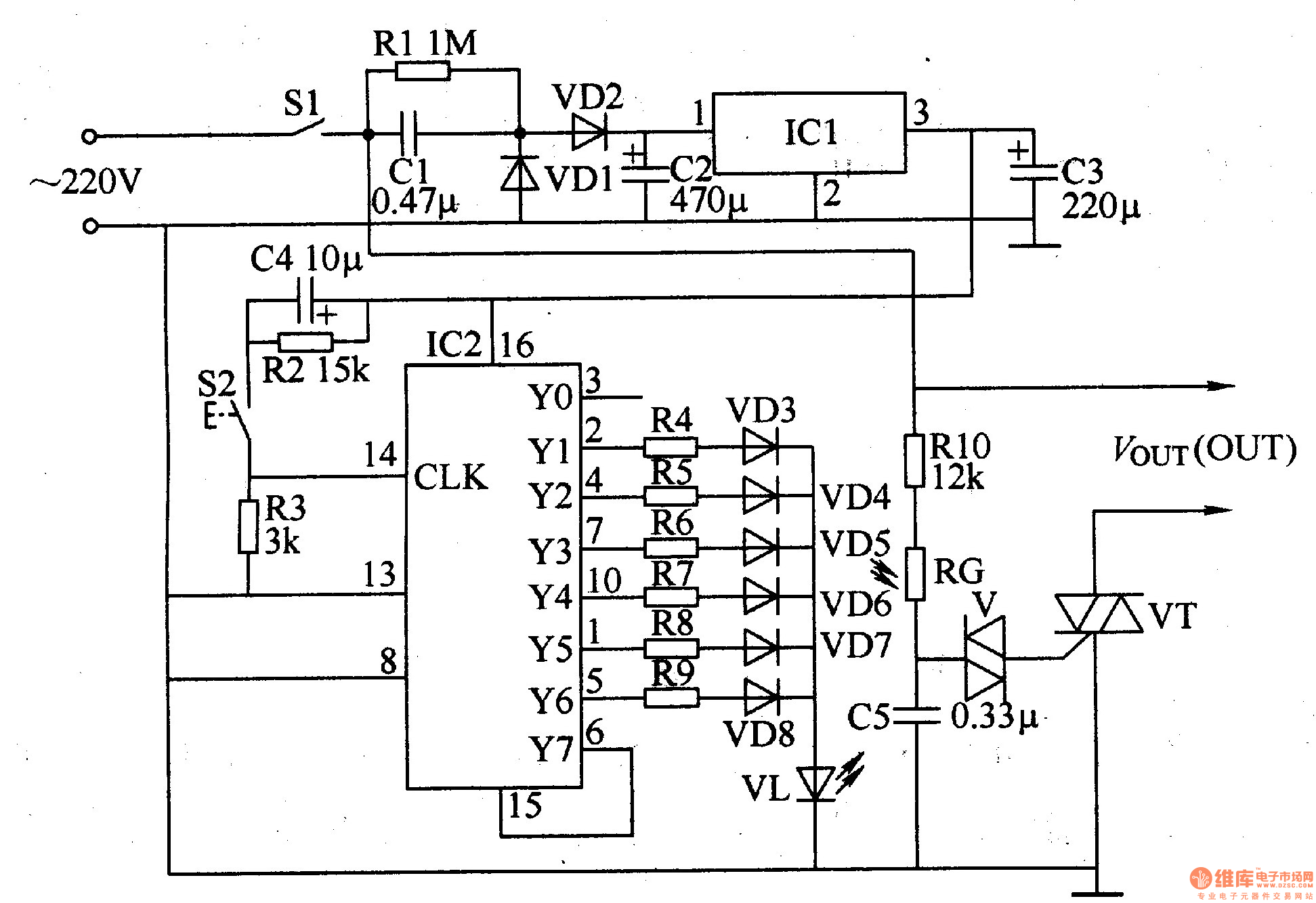
The power circuit is composed of a switch S1, a step-down capacitor C1, a resistor R1, a rectifier diode VD1, a VD2, a three-terminal integrated voltage regulator ICl, and filter capacitors C2 and C3.
IC2 (CD4017) is a decimal counter integrated circuit, and its 14-pin (CLK terminal) is a counting pulse signal input terminal, and an external resistor R3 and a button S2. Each time S2 is pressed, the 14th pin of 1C2 will input a counting pulse. When 52 is continuously pressed, the Yl-Y6 output of IC2 will output high level in sequence. Since the resistance values ​​of the resistors R4-R9 are arranged from small to large, when the different output terminals output a high level, the current flowing through the light-emitting diode VL is also different, so that the luminance of the VL is weakened by the strong.
The light control pulse width modulation circuit is composed of a bidirectional thyristor VT, a bidirectional trigger diode V, a photoresistor RG, a resistor R10, and a capacitor C5.
After the power switch S1 is turned on, the AC 220V voltage is stepped down by Cl, VDl and VD2 are rectified, C2 is filtered, and ICl is regulated, and a voltage of +12V is generated across C3 as the operating voltage of IC2. After each power-on, IC2 is in the initial state, its YO terminal outputs a high level, the LED VL is extinguished, the resistance of the photoresistor RG is the largest (about 2MΩ), the triac VT is cut off, and the circuit "OUT" (Voltage output terminal) · There is no voltage output at the terminal.
When S2 is pressed, the 2 pin (Yl end) of IC2 outputs a high level, so that VL lights up, the resistance value of the photo resistor RG becomes small, and the bidirectional thyristor VT is turned on by the bidirectional diode V. When S2 is pressed again, the 4 pin (Y2 end) of IC2 outputs a high level, the 2 pin returns to a low level, the brightness of VL is slightly enhanced, and the resistance of RC is further lowered, so that the conduction angle of VT is slightly increased. The output voltage at the "OUT" end of the circuit also rises slightly. When S2 is pressed continuously, the 7th pin (Y3 end), 10 pin (Y5 end) and 5 pin (Y6 end) of IC2 will output high level in turn, so that the brightness of VL is stepwise enhanced, and the resistance of RG is gradually reduced. Small, the conduction angle at VT gradually increases, and the output voltage at the "OUT" end gradually increases.
On both ends of the circuit "OUT", the bulb or motor can be connected in parallel for the load. When the voltage at the "OUT" terminal goes high, the brightness of the bulb increases, and the speed of the motor increases. When the voltage at the "OUT" terminal drops, the brightness of the bulb decreases and the speed of the motor decreases.
Component selection
R1-R1O uses 1/4W carbon film resistors.
Both Cl and C5 use polyester capacitors or CBB capacitors with a withstand voltage of 400-600V; C2-C4 selects aluminum electrolytic capacitors with a withstand voltage of 25V.
Both VDl and VD2 use 1N4007 silicon rectifier diodes; VD3-VD8 selects 1N4148 silicon switching diodes.
VL selects φ5mm green high-brightness LED.
V selects the bidirectional diode of type DB3.
VT selects 3A, 600V bidirectional thyristor.
ICl selects LM7812 type three-terminal integrated voltage regulator; IC2 selects CD4017 or CC4017 type decimal counter integrated circuit.
Residual Current Circuit Breaker With Over Load Protection
TWO FUNCTION : MCB AND RCCB FUNCTIONS
leakage breaker is suitable for the leakage protection of the line of AC 50/60Hz, rated voltage single phase 240V, rated current up to 63A. When there is human electricity shock or if the leakage current of the line exceeds the prescribed value, it will automatically cut off the power within 0.1s to protect human safety and prevent the accident due to the current leakage.
leakage breaker can protect against overload and short-circuit. It can be used to protect the line from being overloaded and short-circuited as wellas infrequent changeover of the line in normal situation. It complies with standard of IEC/EN61009-1 and GB16917.1.
RCBO,ELCB,Leakage Circuit Breaker,Residual Current Circuit Breaker,Residual Current Circuit Breaker with Over Load Protection 1p,Residual Current Circuit Breaker with Over Load Protection 2p
Wenzhou Korlen Electric Appliances Co., Ltd. , https://www.zjthermalrelay.com