
Continue with the previous section of the project, here to expand a UART peripheral on the XPS, with the onboard USB2UART chip FT232R to do a high-speed serial transmission test.
First open the previous ISE project, then double-click the mycpu module under the top-level module to open the hardware development platform XPS, as shown in Figure 1.
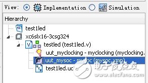
Figure 1 Click to enter XPS
Legend has it that two UART peripheral IP cores are provided on the XPS bus, as shown in Figure 2, namely UART 16550-style and UART-Lite. This section will add a peripheral called UART-Lite, so the name is a streamlined small body UART peripherals, several contacts, and sure enough, the use of this Lite version for complex UART is really embarrassing, but For our experimental study, it is still more good, simple is easy to play, haha. 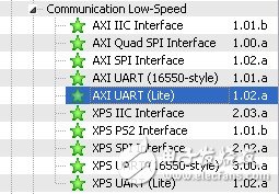
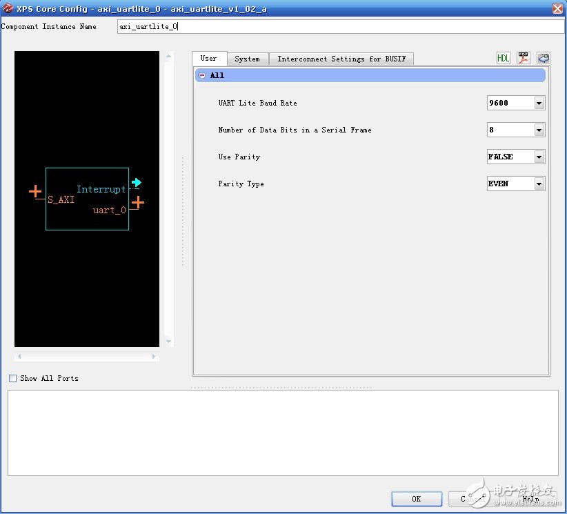
Figure 3 UART-Lite Peripheral Configuration Page
Click on the small pdf icon in the upper right corner of Figure 3 to view the documentation for this peripheral, axi_uartlite_ds741.pdf. As shown in Figure 4, the UART-Lite functional block diagram shows that the peripherals contain the four most basic software-accessible registers, namely the Receive Data FIFO, the Transmit Data FIFO, and the status. Register (Status Register) and Control Register (Control Register). 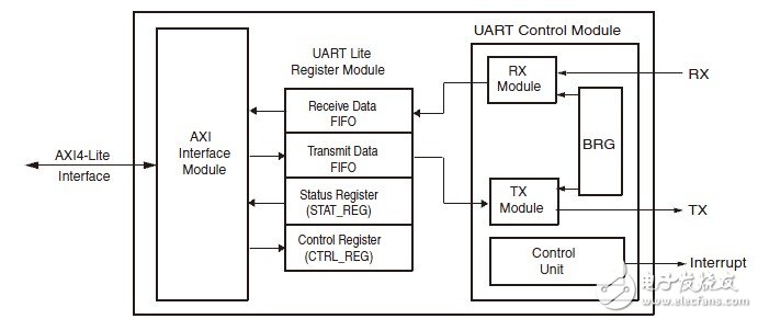
Figure 4 UART-Lite functional block diagram
After completing the UART-Lite configuration, click OK and the serial port shown in Figure 5 will pop up. With the default settings, the AXI bus interface of the UART-Lite peripheral automatically matches the on-chip AXI bus interface on the system's MicroBlaze processor. 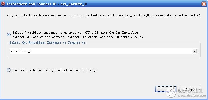
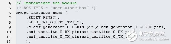
Figure 6 system instantiation template
And re-edited embodiment of the top-level file, the top level code is modified as follows: module testled (clk, rst_n, led, uart_rx, uart_tx); input clk; // 100MHzinput rst_n; // low-level reset signal is output [7: 0] led; // connected to the LED input uart_rx; // UART data reception output uart_tx; // UART data transmission wire clk_100m; // clocking output 100MHzwire clk_50m; // clocking output 50MHzwire clk_25m; // clocking output 25MHzwire clk_12m5; / /clocking output 12.5MHzwire clk_locked; //clocking output completion flag ///--------------------------------- -----------------//IP Core Clocking Wizard instantiation ///---------- Begin Cut here for INSTANTIATION Template ---// INST_TAG myclocking uut_myclocking (// Clock in ports .CLK_IN1 (clk), // iN // Clock out ports .CLK_OUT1 (clk_100m), // OUT .CLK_OUT2 (clk_50m), // OUT .CLK_OUT3 (clk_25m), // OUT. CLK_OUT4(clk_12m5), // OUT // Status and control signals .RESET(!rst_n),// IN .LOCKED(clk_locked) ); // OUT// INST_TAG_END ------ End INSTANTIATION Template --------- //---------------------- -----------------------------// Instantiate the mysoc system (* BOX_TYPE = "user_black_box" *) mysoc uut_mysoc ( .RESET( Rst_n), .LEDS_TRI_O(led), .clock_generator_0_CLKIN_pin(clk_100m), .axi_uartlite_0_RX_pin(uart_rx), .axi_uartlite_0_TX_pin(uart_tx) ); endmodule pin assignment to the top two newly added signal interfaces, adding the following two statements to Testled.ucf can be: NET "uart_rx" LOC = N17; NET "uart_tx" LOC = N18; Finally recompile the entire ISE project and generate a .bit download file. Next, look at the software, open the SDK and locate Workspace to the SDK_workspace directory of the project. We clicked on the system.xml in the mysoc_hw_platform directory. At this point, we found that the new peripheral axi_uartlite_0 did not appear, indicating that the current software project does not update the current hardware project information in real time. 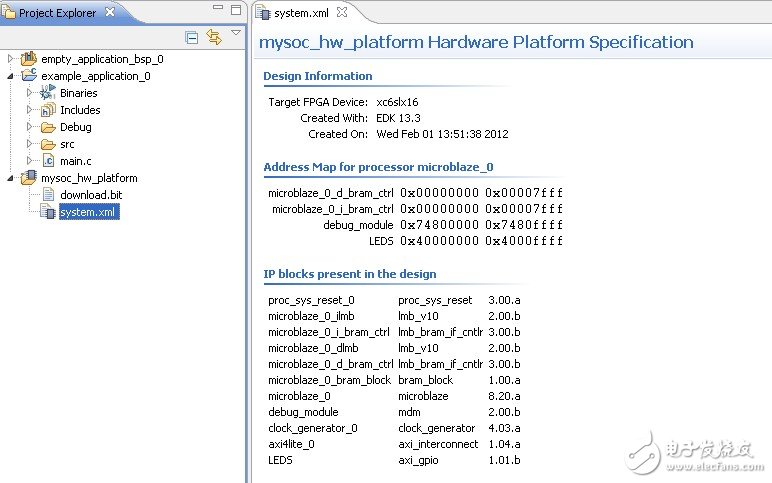
Figure 7 View system.xml
Obviously, in the current situation, we can't program and control the UART peripherals in the software. We must first update the hardware information of the system. Right click on the mysoc_hw_platform folder and select Change Hardware Platform Specification. As shown in Figure 8, relocate system.xml to the current project path (current project folder \mysoc\__xps\system.xml). 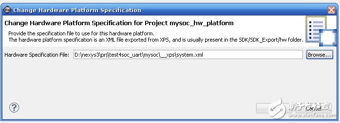
Figure 8 locate system.xml
As shown in Figure 9, the newly added axi_uartlite_0 peripheral of the current instance appears in the rematched system.xml file. 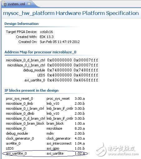
Figure 9 View the new system.xml
Write software test code, realize the query mode (interrupt mode privilege students have not figured out, a little more confused, and then slowly study) serial data reception, and then send the data after negating. /* ------------------------------------------------ ------------ *//* Include File Definitions *//* --------------------------- --------------------------------- */ #include 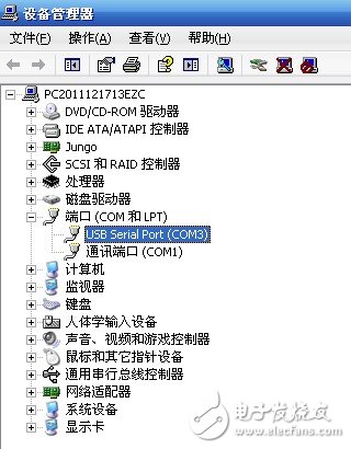
Figure 10 Device Manager's new serial port
As shown in Figure 11, set the serial port debugging assistant port to COM3, baud rate 9600, data bit 8, no parity bit, for communication, send 55AA to return AA55. 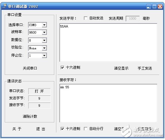
Figure 11 Serial data transmission and reception
Since the FT232 chip uses USB to transmit the UART, it must be a bit too popular to have a reason. Of course, on the one hand, this chip will solve many new PCs without the RS232 serial port, and the old serial port's baud rate is usually no more than 115200bps, so the FT232 will come to challenge, so the privileged students also specially carried out high-speed transmission. The test, the highest nominal 921,600 bps, tossing the old half-day found that it does not work, this down, and finally the privileged classmates simply came to a software test that only did not receive, found that the original AA transmission data on the PC side has become CA or DA. One reasoning is that there may be an error in the peripheral baud rate, so the baud rate is lowered to 460800 bps, OK, and the error of the baud rate is further confirmed. Since the clock of the UART-Lite peripheral is divided by the CPU clock, and the CPU has a baud rate of 50 MHz, there is definitely an error in dividing the value of the non-integer multiple of 921600 bps. This simply solves the problem of raising the CPU clock to 100MHz. In fact, this solution does not solve the baud rate error problem in essence. If it is rigorous, I am afraid that it is more appropriate to adjust the frequency of an integer multiple of 961600bps as the peripheral clock. In short, the specific problem should be analyzed. It turns out that this high-speed UART is still reliable, and in the future it will not be able to get 115200bps on the UART. Reprinted from: privileged classmate's blog
Conecting Terminals Without Screws
Conecting Terminals Without Screws,Cold Pressing Terminals,Low Pressure Cold Shrinkage Terminal,Cold Shrinkage Cable Terminals
Taixing Longyi Terminals Co.,Ltd. , https://www.txlyterminals.com