
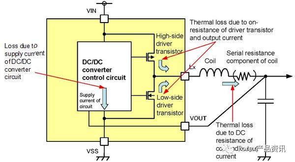
Figure 3 The main power loss part of a step-down DC/DC converter
Among them, in order to improve the efficiency at light load, it is very important to reduce the consumption current of the IC, and the control mode of the IC is extremely critical.
PFM control work and PWM control workHere, the PFM control operation corresponding to the number of load current control switches is very effective. The PFM operation is to reduce the switching time per unit time when the load current is small, and to reduce the inefficient current such as the consumption current and the through current to improve the efficiency. This IC is operated by the PFM to reduce the current consumption at no load to 15 μA or less. As the load current increases, the consumption current of the IC becomes relatively small, and a PWM operation state with a smaller ripple voltage is required at this time.
PWM/PFM automatic switching workThe XC9236 has the ability to automatically switch between PFM operation and PWM operation in response to load changes. This function can simultaneously improve efficiency at light loads and maintain low ripple at heavy loads, which helps improve efficiency over the entire load range. (Refer to Figure 4)
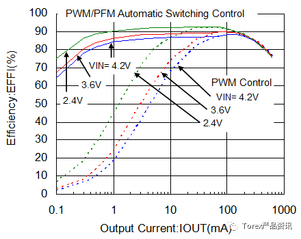
Figure 4 Energy conversion efficiency
From Fig. 5, the load transient response characteristics from PFM operation to PWM operation and reverse transition can be confirmed.
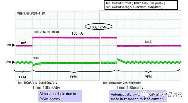
Figure 5 PFM control and PWM control automatic conversion waveform (load current: 1mA⇔100mA)
From the load transient response characteristics when the load changes steeply, it can be recognized that the voltage recovery only starts at the 20mV voltage difference, and no overshoot or ringing occurs at the time of recovery, which makes the phase system have sufficient margin.
Manually switch working stateBased on the automatic PWM/PFM conversion, the XC9237 adds the function of forcing the transition from the external signal to the fixed PWM operation. Corresponding to the use of the machine's working state, it can make it work in the lower ripple PWM working state, can control the noise reduction at any time (refer to Figure 6)
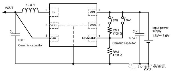
Figure 6 Circuit diagram of the XC9237 manual switching PWM/PFM operation

Solid-state capacitors / Motor starting capacitors
Solid - state capacitors are all called: solid - state Aluminum Electrolytic Capacitors.It with the ordinary capacitance (that is, the liquid aluminum electrolytic capacitors) the biggest difference is that use different dielectric material, liquid aluminum capacitor dielectric material as the electrolyte, and solid-state capacitor dielectric material is conductive polymer materials.Solid-state Capacitors / Motor Starting Capacitors
Solid-state capacitors / Motor starting capacitors,Solid-State Capacitors,Solid-State Small Size Capacitors,Solid-State Low Impedance Capacitors,Long Life Solid-State Capacitors
YANGZHOU POSITIONING TECH CO., LTD. , https://www.yzpst.com