
For "How to build uClinux kernel transplant to S3C44B0X ARMSYS as the core development board," a summary, which includes key elements to modify the functional analysis of Bootloader and kernel releases uClinux2.4.24 basis for the development board S3C44B0X One by one.
2.Bootloader2.1Bootloader Overview
BootLoader is a program that runs before the operating system kernel runs. Through this program, we can initialize the hardware device, establish a map of the memory space, and bring the system's hardware and software environment to a suitable state, in order to prepare the correct environment for the final call of the operating system kernel. Therefore, the prerequisite for the correct establishment of uClinux porting is to have a bootloader that is compatible with uClinux and easy to use.
ARMSYS development board provides such a special bootloader for uClinux. The bootloader program is burned at the address 0x0 of the system. It runs every time it is powered on, and can correctly complete the initialization of the hardware system and the boot of uClinux.
In theory, uClinux does not necessarily require a bootloader that is independent of the kernel. However, separating the bootloader from the kernel can make the software architecture clearer, and it can also flexibly support multiple boot modes and implement some useful auxiliary functions.
The main tasks of the bootloader provided by ARMSYS can be summarized as follows:
1. Hardware initialization
2. Download the new kernel image and file system image from the host;
3. Burn NorFlash and Nandflash;
4. Load the uClinux kernel image and start running;
5. Provides a man-machine interface on the serial HyperTerminal.
2.2 storage space distribution
The bootloader uses the default storage space distribution address to load the uClinux kernel and file system, and correctly guides the operation of uClinux. In the ARMSYS bootloader, the default storage space is distributed as follows:
Content start address storage medium
Bootloader program space 0x00000000Flash
Compressed kernel image 0x00010000Flash
ROM file system image 0x000e0000Flash
Kernel running address 0x0c008000SDRAM
Compressed kernel decompression address 0x0c100000SDRAM
File system loading 0x0c700000SDRAM
The allocation of this storage space is also not fixed, and can be changed by modifying the relevant code in the Bootloader.
2. 3 Bootloader's work
The complete bootloader boot process can be described as follows:
Hardware initialization phase one
â—Ž hardware initialization;
â—Ž copy the secondary interrupt exception vector table;
â—Ž Initialize various processor modes;
â—Ž Copy RO and RW, clear ZI (jump to C code entry function).
Hardware initialization phase two
â—Ž Initialize the hardware devices used in this phase;
â—Ž Establish a human-machine interface;
â—Ž implement image file download and burning tools;
â—Ž Implement the loading and running tools of the image file.
The above steps will be explained one by one, and the contents related to uClinux will be described in detail.
2.3.1 hardware initialization
After the board is powered on or reset, the program starts from the ResetExcepTIonVector at address 0x0. Therefore, the first instruction of the Bootloader needs to be placed here: bResetHandler, jump to the first stage of hardware initialization with the label ResetHandler, the main content is : Turn off the WatchdogTImer, turn off the interrupt, initialize the PLL and clock, and initialize the memory controller. More importantly, the output frequency of the PLL should be calculated correctly. Set it to 64MHz in ARMSYS; this is actually the working frequency of the processor. This time parameter calculates the refresh count value of SDRAM and the baud rate of UART in the second stage. Also used when parameters are used.
2.3.2 Establishing a secondary anomaly interrupt vector table
The Abrupt Interrupt Vector Table (ExcepTIonVectorTable) is one of the key points in the connection between the Bootloader and the uClinux kernel. Even if the uClinux kernel has been controlled by the processor, once the interrupt occurs, the processor will automatically jump to an entry in the first-level exception interrupt vector table starting from the 0x0 address (depending on the interrupt type). Take instruction to run.
When writing a bootloader, the level 1 abort vector table at address 0x0 simply needs to include a jump instruction to the level 2 interrupt vector table. In this way, it is possible to correctly hand over the events to uClinux's interrupt handler for processing. For the uClinux kernel, it establishes its own second-level exception interrupt vector table at the base address of 0xc000000 in RAM space. Therefore, the first-level exception interrupt vector table of the bootloader is as follows:
bResetHandler;ResetHandler
Ldrpc,=0x0c000004;UndefinedInstrucTIonHandler
Ldrpc,=0x0c000008;SOFtwareInterruptHandler
Ldrpc,=0x0c00000c;PrefetchAbortHandler
Ldrpc,=0x0c000010;DataAbortHandler
b.
Ldrpc,=0x0c000018;IRQHandler
Ldrpc,=0x0c00001c;FIQHandler
LTORG
If you do not have to respond to interrupts during the entire execution of the bootloader, the above settings are sufficient. But in our ARMSYS provides a USB downloader, you need to use interrupts, then the bootloader must configure its own secondary interrupt vector table at the same address (0xc000000) to be compatible with uClinux. This table is stored in FlashMemory in advance. During the boot process, it is copied by the Bootloader to the RAM address 0x0C000000 to store the vector table: 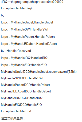
Create a secondary vector table:
;************************************************* ***
;*SetupIRQhandler*
;************************************************* ***
Ldrr0,=(_IRQ_BASEADDRESS+0x100)
Ldrr2, =_IRQ_BASEADDRESS
Addr3,r0,#0x100
0
CMPr0, r3
STRCCr2, [r0], #4; cc: Carryclear; saveR2toR0address, R0=R0+4.
BCC%B0
Ldrr1,=_IRQ_BASEADDRESS
Ldrr0,=ExceptionHanlderBegin;ifthereisn't'subspc,lr,#4'at0x18,0x1c
Ldrr3, =ExceptionHanlderEnd
0
CMPr0,r3;putthevectortableat_IRQ_BASEADDRESS(0xc000000)
LDRCCr2,[r0],#4
STRCCr2,[r1],#4
BCC%B0
Ldrr1,=DIsrIRQ;puttheIRQjudgeprogramat_IRQ_BASEADDRESS+0x80(0xc000080)
Ldrr0,=IsrIRQ;ifthereisn't'subspc,lr,#4'at0x18,0x1c
Ldrr3,=IsrIRQEnd
0
CMPr0, r3
LDRCCr2,[r0],#4
STRCCr2,[r1],#4
BCC%B0
Ldrr1,=MyHandleIRQ;MyHandleIRQpointtoDIsrIRQ
Ldrr0, =ExceptionHanlderBegin
Ldrr4, =_IRQ_BASEADDRESS;
Subr0,r1,r0
Addr0, r0, r4
Ldrr1,=DIsrIRQ
Strr1,[r0]
Define Handlexxx:
^(_IRQ_BASEADDRESS)
HandleReset#4
HandleUndef#4
HandleSWI#4
HandlePabort#4
HandleDabort#4
HandleReserved#4
HandleIRQ#4
HandleFIQ#4
^(_IRQ_BASEADDRESS+0x80)
DIsrIRQ#4
;IntVectorTable
^(_IRQ_BASEADDRESS+0x100)
HandleADC#4
HandleRTC#4
HandleUTXD1#4
HandleUTXD0#4
HandleSIO#4
HandleIIC#4
HandleURXD1#4
HandleURXD0#4
HandleTIMER5#4
HandleTIMER4#4
HandleTIMER3#4
HandleTIMER2#4
HandleTIMER1#4
HandleTIMER0#4
HandleUERR01#4
HandleWDT#4
HandleBDMA1#4
HandleBDMA0#4
HandleZDMA1#4
HandleZDMA0#4
HandleTICK#4
HandleEINT4567#4
HandleEINT3#4
HandleEINT2#4
HandleEINT1#4
HandleEINT0#4
Reconstructing the abort vector to SDRAM has the advantage of arbitrarily assigning the address of the interrupt handler within other functional programs. To this end, we are at 44b. Defined in the h file:
/*ISR*/
#definepISR_RESET(*(unsigned*)(_IRQ_BASEADDRESS+0x0))
#definepISR_UNDEF(*(unsigned*)(_IRQ_BASEADDRESS+0x4))
#definepISR_SWI(*(unsigned*)(_IRQ_BASEADDRESS+0x8))
#definepISR_PABORT(*(unsigned*)(_IRQ_BASEADDRESS+0xc))
#definepISR_DABORT(*(unsigned*)(_IRQ_BASEADDRESS+0x10))
#definepISR_RESERVED(*(unsigned*)(_IRQ_BASEADDRESS+0x14))
#definepISR_IRQ(*(unsigned*)(_IRQ_BASEADDRESS+0x18))
#definepISR_FIQ(*(unsigned*)(_IRQ_BASEADDRESS+0x1c))
#definepISR_ADC(*(unsigned*)(_IRQ_BASEADDRESS+0x100))//0x20))
#definepISR_RTC(*(unsigned*)(_IRQ_BASEADDRESS+0x104))//0x24))
#definepISR_UTXD1(*(unsigned*)(_IRQ_BASEADDRESS+0x108))//0x28))
#definepISR_UTXD0(*(unsigned*)(_IRQ_BASEADDRESS+0x10c))//0x2c))
#definepISR_SIO(*(unsigned*)(_IRQ_BASEADDRESS+0x110))//0x30))
#definepISR_IIC(*(unsigned*)(_IRQ_BASEADDRESS+0x114))//0x34))
#definepISR_URXD1(*(unsigned*)(_IRQ_BASEADDRESS+0x118))//0x38))
#definepISR_URXD0(*(unsigned*)(_IRQ_BASEADDRESS+0x11c))//0x3c))
#definepISR_TIMER5(*(unsigned*)(_IRQ_BASEADDRESS+0x120))//0x40))
#definepISR_TIMER4(*(unsigned*)(_IRQ_BASEADDRESS+0x124))//0x44))
#definepISR_TIMER3(*(unsigned*)(_IRQ_BASEADDRESS+0x128))//0x48))
#definepISR_TIMER2(*(unsigned*)(_IRQ_BASEADDRESS+0x12c))//0x4c))
#definepISR_TIMER1(*(unsigned*)(_IRQ_BASEADDRESS+0x130))//0x50))
#definepISR_TIMER0(*(unsigned*)(_IRQ_BASEADDRESS+0x134))//0x54))
#definepISR_UERR01(*(unsigned*)(_IRQ_BASEADDRESS+0x138))//0x58))
#definepISR_WDT(*(unsigned*)(_IRQ_BASEADDRESS+0x13c))//0x5c))
#definepISR_BDMA1(*(unsigned*)(_IRQ_BASEADDRESS+0x140))//0x60))
#definepISR_BDMA0(*(unsigned*)(_IRQ_BASEADDRESS+0x144))//0x64))
#definepISR_ZDMA1(*(unsigned*)(_IRQ_BASEADDRESS+0x148))//0x68))
#definepISR_ZDMA0(*(unsigned*)(_IRQ_BASEADDRESS+0x14c))//0x6c))
#definepISR_TICK(*(unsigned*)(_IRQ_BASEADDRESS+0x150))//0x70))
#definepISR_EINT4567(*(unsigned*)(_IRQ_BASEADDRESS+0x154))//0x74))
#definepISR_EINT3(*(unsigned*)(_IRQ_BASEADDRESS+0x158))//0x78))
#definepISR_EINT2(*(unsigned*)(_IRQ_BASEADDRESS+0x15c))//0x7c))
#definepISR_EINT1(*(unsigned*)(_IRQ_BASEADDRESS+0x160))//0x80))
#definepISR_EINT0(*(unsigned*)(_IRQ_BASEADDRESS+0x164))//0x84))
For example, we need to use the Exint4567 interrupt, and after defining the interrupt handler Meint4567Isr(), we only need one statement:
pISR_EINT4567=(int)MEint4567Isr;
It will make it possible to jump to the handler we wrote correctly after the interrupt occurs.
Flex Power Supply,Flex Power Supply 80Plus,700W Adapter Server Power Supply,Flex 700W Power Supply
Boluo Xurong Electronics Co., Ltd. , https://www.greenleaf-pc.com