
The LED bracket is the substrate of the LED lamp bead before the package, which functions to protect the solid crystal bonding wire and the silicone molding, and turns on the circuit and affects the optical and electrical characteristics. The performance of the structure of the bracket directly affects the performance of the LED lamp bead. At present, many lamp beads are dead. After the microscope observation, the chip in the lamp bead does not appear abnormal, but the alloy wire connecting the chip is separated from the metal substrate to cause an open circuit. As shown in Figure 1.
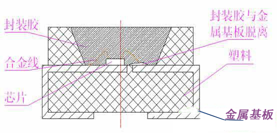
   Figure 1: The alloy wire connecting the chip is separated from the metal substrate to cause an open circuit.
At the same time, it was found that the lamp beads causing this phenomenon were directly or indirectly exposed to the air, and there was moisture in the air. It can be inferred that the anti-moisture structure of the LED bracket is not well made, causing moisture to penetrate into the lamp bead, thereby causing the encapsulant to be easily detached from the metal substrate in the environment where the LED lamp bead is long-term lit, so that the unplugging is welded. An alloy wire on a metal substrate to form a circuit break.
With the increasing demand for LEDs in the global light source market, the use of LED lamp beads is becoming wider and wider, and users are increasingly demanding the performance of LED lamp beads. If the moisture-proof structure of the LED holder is not well designed, it is inevitable to limit the use conditions, use areas, fields of use, and the like of the LED lamp bead. As an LED designer and manufacturer, there must be a breakthrough in the moisture-proof structure of the LED bracket.
First, the basic knowledge of liquid flow
The nature of the flowing liquid is between the gas and the liquid. On the one hand, it is like a solid, has a certain volume, is not easy to compress; on the other hand, it is like a gas, has no certain shape, and has fluidity. The flowing liquid is affected by inertia force, viscous force, etc., and the pressure in any direction in the interior is not equal.
The flowing liquid will be subjected to the resistance along the path and the local resistance along the way. The mechanical energy loss caused by the resistance along the path is called the loss along the path. The energy loss that overcomes the local resistance is called the local loss. The energy loss of all flowing liquids is equal to the sum of the losses along the sections and the local losses.
Second, the five points of moisture-proof structural design
The moisture-proof structural design, as its name suggests, is to keep the moisture out of the way, or to stop the flow of moisture inside it. The plastic and metal substrate of the bracket are two different materials. The external force is used to bond the two together. It is a physical bond. Even if the adhesive flaw is not visible to the naked eye, on a magnifying glass of several tens of times, There must be a gap on the interface, as shown in Figure 2. This determines that the bracket cannot keep the moisture out of the body, which means that moisture will penetrate into it. Therefore, the moisture-proof structure design of the bracket, in a strict sense, relies on the related structural design within it to reduce the fluid that penetrates into it. To reduce the fluid, that is to say, all the energy of the fluid is lost as much as possible in each loss of path and local loss.
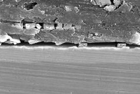
   Figure 2: There is a gap between the plastic and the metal substrate of the bracket after the physical bonding
Experiment with the TOP VIEW model bracket, immerse the empty bracket in the red ink, and red ink is slightly covered on the bracket pin (Note: If you want to make the experiment more obvious, pour alcohol into the red ink, the proportion The mixture was stirred at 1:1, and the experiment was terminated after 5 minutes. The whole process was observed with a microscope to observe the inside of the stent cup. The experimental conclusion is that some stents seep quickly, some stents seep slowly, some stents seep slightly, and some stents seep heavily. Take some of the brackets after the experiment, and immediately cut them along the gap between the plastic and the metal substrate with a cutting pliers. It can be found that there are red ink marks on the surface and edges of the metal substrate. Therefore, it can be concluded from the experiment that there are two ways for red ink to penetrate into the body of the stent, one is the edge of the copper wrapped with plastic, the other is the surface of the copper wrapped with plastic, and the front and back of the copper are the same. The former is more serious.
To solve the above arguments, we can solve the problem from three aspects: First, seek the best cooperation between plastic and metal substrate, which is related to the knowledge of materials science, not in the scope of this article; second, the plastic injection molding process, the pursuit of the most Good mold temperature and die time, which is related to the content of the injection molding process, and is not analyzed in this paper; the third is the treatment on the metal substrate, which is the moisture-proof structure design mentioned in this paper.
The main points of moisture-proof structural design are:
1. Extend the edge of the metal substrate as much as possible, and fold back and forth, the more twisted the better.
2. Minimize the contact area between the metal substrate and the plastic. Of course, this conflicts with the thermal design. Both need to be compromised or sacrificed to find the best design. Here, there is no detailed analysis of the thermal design.
3. Make some water-blocking walls such as grooves on the surface of the metal substrate, increase the roughness of the surface of the metal substrate, and increase the difficulty of liquid flow. Of course, the shape of the water-blocking wall is more exaggerated, but considering the difficulty of production and the cost of production. It is suitable.
4. Reducing the area of ​​the metal substrate into the plastic port is equivalent to reducing the way liquid enters the holder.
5. Lead the liquid into the non-stent cup as much as possible.
Specific analysis of three and seven kinds of bracket moisture-proof structural design schemes
With the continuous advancement of the mold industry, stamping, drilling and milling, bending, and injection molding processes are increasingly able to achieve precise and complex design concepts. The design content of the moisture-proof structure of the bracket is constantly updated and continues to break through. The designer pursues the cost performance of the product. While designing the moisture-proof structure well, it also needs to take into account other aspects of performance, such as heat, electricity, and light performance, and more attention to processing difficulty and processing cost.
Considering the main points of moisture-proof structural design, the moisture-proof design lists the following various schemes and comprehensively analyzes its advantages and disadvantages.
Scheme 1: Metal substrate flat type. The metal substrate is not treated at all, and the positive and negative two different polarities are simply distinguished, as shown in Fig. 3. The design concept is not added with moisture prevention, the processing cost is low, but the airtightness is poor. The lamp beads made by this kind of bracket are only guaranteed to be lit, but in the place where there is moisture, the dead light will appear soon. Or use waterproof glue on the outside of the lamp bead to use, which indirectly increases the cost of using the client.
Option 2: Extend the edge path of the metal substrate. In the existing bracket design, the design concept of “extending the edge of the metal substrate†has been added. Figure 4 is a purple circle. By punching the edges of the metal substrate into different degrees of curves, the more complicated the curve is, the longer the edge line of the metal substrate is, which greatly increases the difficulty of moisture infiltration from the edge of the metal substrate. Of course, the more the edge line of the metal substrate is processed, the higher the processing cost, and the performance of the metal substrate is also required to be good.
Option 3: Plastic wrapped side pins, the existing manufacturing process of the general bracket is: metal substrate stamping forming → plating → injection molding → bending and cutting. The drawback is that moisture can penetrate on the side of the pin. In order to allow the moisture to penetrate longer, the plastic can wrap the side pins and expose only the bottom pins as conductive legs. As shown in the purple circle in Figure 5. The manufacturing process of the bracket was changed to: metal substrate stamping forming → electroplating → first bending → injection molding → second bending and cutting. In this way, the plastic wraps the metal substrate well inside. But as you can see from the production process, such a solution is more complicated. If a few holes are punched in the first bend of the metal substrate, the effect will be more obvious. Of course, this also increases the processing cost. This design scheme will cause difficulties in the process of soldering on the client side. If the amount of tin on both sides of the pin is uneven, it is easy to cause the lamp bead to tilt.
Solution 4: Reduce the contact area between the metal substrate and the plastic. In the existing bracket design, the design concept of "reducing the contact area between the metal substrate and the plastic" is also added. As shown in the purple circle in Figure 6. By punching out several holes of different degrees on the surface of the metal substrate, there are squares, circles, etc., the more holes, the more obvious the effect. The number of holes must be determined by the properties of the metal substrate. Elsewhere, the choice of hole location is also critical, and the hole is generally limited to the vicinity of the important position in the cup body, and should not be designed at a position far from the cup. The advantages of this scheme are two: one is that the upper and lower plastics can be tightly tightened, and the metal substrate is tightly clamped; the second is to reduce the interface between the plastic and the metal substrate, and better avoid the existence of plastic and metal substrates. The gap. These two benefits are well protected against moisture infiltration. Of course, this also increases the processing cost.
Option 5: Increase the roughness of the surface of the metal substrate. In the existing bracket design, the design concept of “increasing the roughness of the surface of the metal substrate†is also common. As shown in the purple circle in Figure 7. In theory, this scheme prolongs the way in which moisture penetrates into the surface of the metal substrate and increases the difficulty of moisture flow. However, if the water-repellent wall and the pitting of the surface of the metal substrate are too exaggerated or improperly designed, it is easy to cause a reverse effect, that is, the contact area between the metal substrate and the plastic is increased, and the interface gap between the two is more likely to occur. . Therefore, increasing the roughness of the surface of the metal substrate should be adequate, and there should be a certain proportion in a certain area, and the specifics are not studied in depth.
Solution 6: The metal substrate in the non-cup is not plated or roughened. According to the design concept of "increasing the roughness of the surface of the metal substrate", the metal substrate in the non-cup body can be not plated or roughened. Generally, the plating surface is smoother than the non-plated layer, so that the plastic and the metal substrate are more firmly bonded. However, if the non-cup is not electroplated, the metal substrate is easily oxidized in a humidified high temperature environment, so that the metal substrate wrapped in the plastic is rusted, causing a larger gap between the two interfaces. For a long time, the oxidized region will Extending to the plated metal substrate in the cup, the consequences can be imagined. If the plating in the non-cup body is rough, the plating in the cup body is smooth, so that the electroplating process is complicated and the manufacturing cost is also increased accordingly. Therefore, this program is not recommended.
Option 7: Reduce the port area of ​​the metal substrate into the plastic. In theory, starting at the moisture inlet end, reducing its area or port, reducing the amount of water vapor infiltration, can play a good role in preventing moisture infiltration. A large hole is punched out at the advancing end of the metal substrate, so that the formed bracket and the metal substrate extend into the plastic portion have only two ends left. The plastic-wrapped metal substrate is more secure, and the gap between the two interfaces is not apparent in appearance. However, the experiment verified that the actual effect of this is not obvious. It has been analyzed that moisture infiltration does not exist periodically and quantitatively, but exists in the air for a long time. Even if the infiltration port of moisture is small, it will eventually infiltrate under long-term action.
Fourth, the alternative conjecture of the structure of the moisture-proof structure of the bracket
Based on the key points of moisture-proof structural design, you can have a more imaginative space.
Option 8: Assume that there is no need to consider the light reflected by the bright plating layer on the bottom of the holder cup (Note: according to the material science and the current plating process, the whiteness reflectance of the plastic is 0.92, and the reflectivity of the plating layer is 0.97). During injection molding, a thin layer of plastic can also be injected into the bottom of the holder cup, leaving only the fixed solid crystal area and the wire bond area, and the rest are sealed with plastic. As shown in the purple circle in Figure 9. In this way, the infiltration path of water vapor is further extended. In theory, the moisture-proof effect will be more obvious.
Scheme 9: The above various schemes are designed from the viewpoint of “all the energy of the fluid is lost as much as possible in each loss along the path and the local lossâ€. If the idea is changed, after the moisture infiltration, consider how to Most of the moisture is transferred to other non-primary parts. Thus, although moisture is infiltrated, it does not penetrate into the holder cup, so that the performance of the final product is not affected.
Only one side of the wire bonding area is designed, and the other side does not extend into the body of the bracket, and the portion of the body that protrudes into the body of the bracket is designed with as many water retaining walls as possible, and the other end is not planned, as simple as possible. From the theoretical analysis of the flow of liquids, liquids tend to flow more easily to areas where there is no resistance, and most of them. Thus, most of the infiltrated water vapor flows to the end of the figure B, which is well protected from moisture infiltration into the portion A of the figure.
Option 10: In the same way as Scheme 9, the shape of the bracket is made larger, and more metal substrate circuit design needs to be made in the plastic. As shown in FIG. 11, the AB end is the main metal substrate in the cup body, which is the LED lamp bead wire bonding area, and the CD end is an auxiliary metal substrate. The metal substrate line at the AB end is designed with as many water retaining walls as possible, and the CD end is not planned as simple as possible. Thus, moisture is more likely to penetrate into the CD end, and the moisture capacity is larger.
However, in order to achieve the above theoretical effect, the difficulty of infiltrating the AB end and the penetration into the CD end are greatly different, otherwise the moisture will infiltrate into the AB end more or less. It can be seen that this solution not only increases the cost of plastics, but also increases the cost of metal substrate processing, so it should not be promoted.
V. Comparison of various design schemes
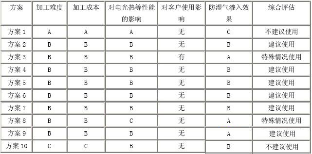
(Note: The comparison is based on the relative comparison of 10 schemes, there is no absolute relationship. The difficulty of processing is represented by A→C is easy → difficult; the processing cost is represented by A→C low → high; the influence on the performance of electro-optic heat is A →C stands for good effect→poor effect; anti-moisture infiltration effect is good by A→C→poor effect. Comprehensive evaluation: recommended use means that multiple schemes can be used together, and special circumstances are used under certain requirements. .)
The moisture-proof structure design of the LED bracket is proposed under the condition that the LED usage conditions are more and more severe, and the development is very fast. Products should focus on cost-effectiveness, and choose the best-in-class design without considering other factors such as cost and customer usage conditions. A single solution can not meet the requirements. It is recommended to use a variety of solutions together, so that the process work will not be increased due to the complexity of the structure, and the processing cost will not increase exponentially, but the effect can be doubled.
The LED industry is driving, which can drive the development of the mold industry, electroplating industry, material industry, etc., while breakthroughs in certain technologies of other manufacturing industries can also provide technical guarantee for the innovative design of the LED industry. It is believed that under the influence of the development of various industries, the design scheme of LED brackets will emerge in an endless stream, there will be more reliable technical guarantees, and new thinking ideas can be realized.
Shanghai Janetec Electric Co., Ltd. , https://www.janetecelectric.com