
The ACDC switching power supply has an important technical parameter - power-down hold time, which is the time difference ⊿t from the AC power-down to the output voltage drop to the accuracy range (usually -2%), as shown in Figure 1. In layman's terms, how long the output can last after the switching power supply is not input.
In many cases, after detecting that the AC is powered off, the system needs to save and transfer the data, set the state of the actuator, and so on. Therefore, after the AC is powered down, the switching power supply needs to continue to supply power to the system for a period of time to ensure reliable shutdown of the system. In addition, in a system with a UPS, the switching power supply is required to maintain a normal output during the process of switching from the mains to the UPS.
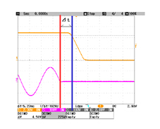
Figure 1 Schematic diagram of power down retention time
1 Determinants of power down retention time
The block diagram of the conventional ACDC switching power supply is shown in Figure 2. After the AC input is rectified and filtered, it becomes a DC voltage (with a certain ripple voltage), and then converted into the voltage output we need through the DCDC converter. The control circuit adjusts the duty cycle (PWM mode) based on the input voltage and output load to achieve a stable voltage output. After the AC input is powered down, the energy stored by the input filter capacitor supplies power to the output. In this process, the filter capacitor voltage gradually decreases, and the control circuit can still achieve the rated output voltage by adjusting the duty cycle until the capacitor voltage drops to control. When the circuit can be adjusted outside the range, the output voltage begins to drop.
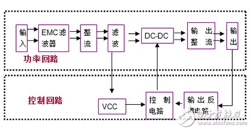
Figure 2 ACDC switching power supply block diagram
We use examples to illustrate the factors that determine the time to power down. Assume that a product with Vo=5V, Po=20W, and efficiency of η=0.78, the minimum voltage of the DC-DC part that can work normally is Vin_min=100V, and the internal input filter capacitor of the power supply is Cin=47uF. Assume that the nominal 220Vac input rectified and filtered voltage is DC voltage (actually has a certain ripple), its value Vin_nor=308V, according to the conservation of energy, there is the following formula:
0.5*Cin*(Vin_mor2-Vin_min2)=⊿t*Po/η......(1)
Substituting the value can be obtained: ⊿t=77.9ms.
As can be seen from the above equation, ⊿t is proportional to the input capacitance, AC input voltage, and product efficiency, and inversely proportional to the output power and the minimum operating voltage of the DC-DC section.
In an actual engineering environment, the input voltage is fixed. For a specific AC-DC power supply product, the internal input filter capacitor Cin, DC-DC part of the minimum operating voltage Vin_min, efficiency η can not be changed, so the power supply's own power-down retention time can not be changed. Through the peripheral adjustment, it is also impossible to change the Vin_min and η of the product. The only thing that can be adjusted is to connect the first-stage rectification filter at the front end of the power supply. The external filter capacitor is connected in parallel with the input filter capacitor inside the power supply, which increases the Cin and increases. The power down time is maintained.
If the filter capacitor added to the front end of the power supply is 100uF/400V, the power-down hold time is increased by 165.7ms on the previous basis. If the power supply operates under a half load condition, the power down hold time can be doubled again, as shown in Table 1.
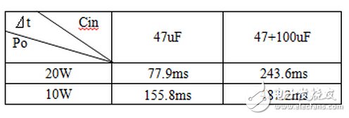
Table 1 Table of power-down retention time and input capacitance and load
2 Effect of output capacitor on power-down retention time
Under the above conditions, we calculate the effect of extending the power-down holding time by increasing the output capacitance Co. Assume that the output voltage accuracy is ±2%, and the output voltage lower limit Vo1=4.9V, Co=40000uF, then:
0.5*Co*(Vo2-Vo12)=⊿t1*Po......(2)
Substituting the value can be obtained: ⊿t1=1ms.
We found that the output of the 40000uF capacitor extended the power-down retention time of only 1ms! It can be seen that the effect of increasing the output capacitance on the power-down retention time is minimal.
3 recommended peripheral circuits
As shown in Figure 3, the input terminal of the peripheral circuit is connected to the mains, and the output can be equivalent to a DC power supply, which is connected to L and N of the ACDC switching power supply. C1 is determined based on the actual load, input voltage, and required hold time. There are no clear recommendations. Since the C1 is increased, the starting surge current will increase, and R1 can be used to reduce the inrush current. A 3W winding resistance can be selected, and the resistance is approximately between 2 and 7.5 ohms. For D1, 1000V and 1.5A and above rectifier bridges can be selected. In addition, the surge current that the rectifier bridge can withstand (specified in the specification) should be larger than the inrush current in the actual circuit.
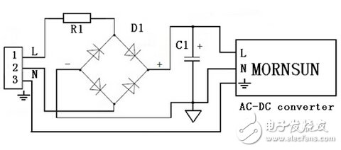
Figure 3 peripheral recommended circuit
4 test results and analysis
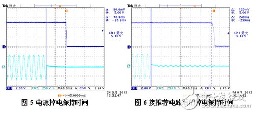
In order to verify the correctness of theoretical analysis and calculation, MORNSUN's LH25-10B05 was selected for testing. Under the condition of input voltage 220Vac and load 4A, the power-down retention time of LH25-10B05 is 76.8ms, the waveform is shown in Figure 5. After the recommended circuit is connected with 100uF/400V input filter capacitor, the power-off retention time of the power supply is increased to 249ms, the waveform is shown in Figure 6. The test results are in agreement with the theoretical calculations.
Cable Barcode Scanner,Barcode Scanner Cable,Symbol Scanner Cable,Barcode Scanner Usb Cable
Guangzhou Winson Information Technology Co., Ltd. , https://www.barcodescanner-2d.com