
The LIN protocol is suitable for low-cost, short-range, low-speed network communication in automobiles, and its purpose is to transmit the switch setting state and respond to changes in the switch. This paper analyzes the characteristics of the LIN bus protocol, the composition of the message protocol, the error detection mechanism, etc., and describes how to implement the LIN bus slave node based on the PICmicro device.
The LIN protocol was developed by the European Association of Vehicle Manufacturers for low-cost, short-range, low-speed network communications. Its purpose is to transmit switch settings and respond to changes in switching, so communication events occur over a hundred milliseconds, without Other faster automotive applications like engine management. This protocol supports bidirectional communication on a single wire, using a low cost microcontroller driven by an RC oscillator, which eliminates the cost of a crystal or ceramic oscillator. In addition, this protocol actually exchanges cost savings on hardware at the cost of time and software. Each message of the LIN protocol contains auto-baud stepping data, which can support a baud rate of up to 20k, while the low-power sleep mode can shut down the bus to avoid unnecessary power consumption. The bus can be powered by any one of the nodes.
LIN bus characteristicsThe LIN bus combines the features of I2C and RS232: Like the I2C bus, the LIN bus is pulled up to a high level by a resistor, and each node can pull the bus low through the open collector driver; The bit and stop bits identify each byte, and each bit is transmitted asynchronously on the clock.
Figure 1 shows a typical LIN protocol configuration. When any node pulls the bus low, the bus is low, which indicates that the bus enters the occupied state; and when all the nodes make the bus floating, the bus is at the battery voltage (9-18V), which means the bus is not Recessive state; a bus that floats in an idle state is pulled up to a high level by a resistor.
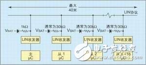
The bus operates at 9 to 18 volts, but all devices connected to the bus must be able to withstand 40V. In general, the microcontroller is isolated from the bus by a line driver or receiver. The bus is terminated to Vbat on each node, the master node is terminated by a 1kΩ resistor and the slave node is terminated by a 20kΩ to 47kΩ resistor. The maximum length of the bus is 40 meters.
Each byte transmitted on the bus is framed together with the start and stop bits. The start bit has the opposite state of the idle state (ie, 0), while the stop bit is the same as the idle state. In each byte, the least significant bit is transmitted first.
Message protocolThe way the master node controls the bus is to poll each slave node and share the slave node's data with the rest of the bus. The slave node only performs data transfer when it receives a command from the master node, so that bidirectional transmission is possible and no further arbitration is required. The message transmission starts with a synchronous interrupt sent by the master node, followed by the synchronization field and message field of the message. The clock of the entire bus is also set by the sync field transmitted at the beginning of each message, and each slave node uses this byte to adjust its baud rate.
The synchronous interrupt puts the bus into an occupied state, which is the transmission time of the 13-bit data, followed by a stop bit (non-occupied state), which tells the slave that there is a message transmission. The clock drift of the master and slave nodes is allowed to be at most 15%, so the synchronization interrupt received from the node may have only 11 bits or up to 15 bits of data.
The second byte of each message is the flag byte that tells the bus what data is being transmitted after the byte and which node should respond, and the length of the response (the flag field is shown in Figure 2). Only one slave node responds to a command, and the slave sends data only under the direction of the master node. As long as the data appears on the bus, every node can receive it. Therefore, it is not necessary for the master node to specifically control the communication between the slave nodes.
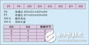
Since the design uses a cheap RC oscillator, the slave node must detect the master node's baud rate and adjust its current baud rate at each transmission. Therefore, each communication begins with a sync byte consisting of alternating "0"s and "1s". The identity field follows the sync field, which tells what is being transmitted behind the bus. The identification field is further divided into three subfields. The lowest 4 bits (0-3 bits) are the devices on the addressing bus. The middle two bits (4-5 bits) are the length of the message transmitted later, the highest two bits (6-7). ) used as a parity bit.
In addition to the sleep command, the LIN protocol does not define the content of each message. Other commands are defined by the specific application.
Error detection mechanismThe errors described below must be detected and counted within each node.
Bit Error - The transmitting node must compare the data bits it believes should be transmitted with the data bits actually present on the bus. Since the bus requires response time, the controller must wait long enough before detecting the data bits. Assuming a minimum voltage rollover rate of 1V/μs and a bus maximum voltage of 18V, the transmitter must wait 18μs to detect if the data bits on the bus are correct.
Checksum Error - The content of each message is protected by a checksum byte.
Parity Error - The 6 data bits of the command byte are protected by two parity bits, which need to be recalculated and compared. If an error occurs, the current command should be ignored and an error should be logged. There is no direct error reporting mechanism in the LIN protocol, but each slave node should track its own errors, and the master node can ask the slave node to transmit the error status as part of the normal message protocol.
LIN bus and CAN busThe LIN protocol is not directly compatible with the CAN bus, but it is expected that the two will interoperate. The CAN bus may be used throughout the car to communicate, while the LIN bus is only used in the car's local circuits, such as the door. In order to connect the two buses, a CAN-LIN protocol interface node is needed, which collects information from the LIN bus node and transmits it to the CAN bus.
Low-power sleep modeThe master node instructs all nodes to enter sleep mode by transmitting an identification code of 0x80, and the contents of the data bytes following the sleep command are not defined. The slave node that receives the sleep command should set itself to wake up when the bus changes and turn off its own voltage to minimize current consumption. The bus will be high and will not consume current when in sleep mode.
Any node can wake up the bus by sending a wake-up signal. When a wake-up signal is received, in general all nodes should be active and wait for the master to initiate bus polling.
Hardware example
Figure 3 shows an example of hardware with two buttons and three LEDs. Each time the button 10 is pressed, the LED1 changes state once. Similarly, each time the button 2 is pressed, the LED 2 changes state once. As a response identified as ID1, the number of presses of the button is transferred to the bus. As a response identified as ID4, a refresh of the number of presses of the button is transmitted to the bus.
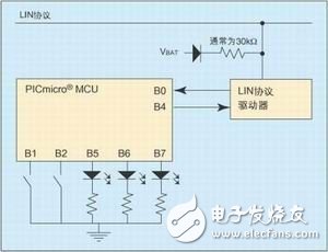
The LIN protocol program operates under an interrupt triggered by RB0 to implement bus sleep/wake. When an interrupt is triggered, the program counts the length of the low-level data bits, then reads the sync byte and determines the data bit time, and finally compares it to the original data bit time to determine if the initial low time is When the time is greater than 10 data bits, more than 10 is a synchronous interrupt, and less than 10 is a wake-up signal. If it is a wake-up signal, the program exits and continues to wait for the synchronous interrupt; if it is a synchronous interrupt, the program reads the command byte, checks the parity and checks the action table (acTIon table) to determine the next action. The action table defines the source or destination of the data on the bus.
In order to initialize the Slavehandler of the LIN protocol, the user must call the InitLinSlave program, which initializes the RB0 interrupt pin and the TMR0 register. The TMR0 register is used to measure the length of the data bits and generate the baud rate. After the initialization is complete, the user can execute their own program. Once the falling edge on the RB0 pin is detected, the user program will be interrupted. When a falling edge is detected, the program jumps to the interrupt service routine. All interrupt sources except TMR0 and RB0 interrupts must be disabled in order to make accurate measurements of the sync field. After calculating the baud rate, the interrupt service routine exits execution.
At the next RB0 interrupt, the LIN protocol Slavehandler automatically enters receive mode to receive the identification field or data byte. If the start bit of the identification field is detected, the identification field is received and decoded. The corresponding code is then executed based on the received identification, such as storing data or lighting the LED. The flag FCOMPLETE is set after a frame transfer on the bus is completed. This flag indicates that all data has been correctly received and can be processed later. This flag is cleared by the user firmware.
The LIN protocol slave handle Slavehandler can work at a baud rate of 20K, requiring 420 words of program storage space and 23 bytes of data storage space.
Due to its low cost, the LIN protocol has the potential to be widely adopted in automotive applications. Microprocessors such as Microchip's various devices can be used with a built-in RC oscillator and run at a 4MHz clock frequency, enabling designers to design applications at the lowest possible cost
2000W Digital Tv Transmitter,Wireless Fm Digital Transmitter,2Kw Wireless Digital Tv Transmitter,2Kw Video Digital Tv Transmitter
Anshan Yuexing Technology Electronics Co., LTD , https://www.yxhtfmtv.com