
Now in some portable electronic products, especially when it is necessary to drive multiple LEDs, a boost circuit is required. The conventional inverters do not meet the current characteristics of miniaturization and integration of electronic products, so they are usually adopted in DC/DC systems. Charge pump technology, the design idea of ​​the soc can be used to integrate the boost module into ic to achieve boosts of 1x, 1.5x, and 2x. The following briefly describes the working principle of the charge-type Charge Pump (also has an inductive Charge Pump, not described here).
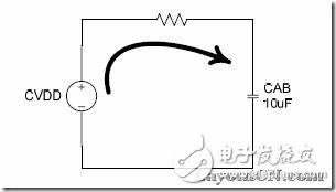
Charge Pump, also known as charge mercury, is based on the simple principle: Q=C*U. C is fixed. If the voltage is large, the power is also large. The boosting process can be represented by the following figure:
The following is a brief introduction of this process using Fujing's FS9821 (MSP type):
FS982x is a MSP, working voltage 2.2-3.6V, internal 14bit (actual 24bit), 6ch ADC, built-in 1-2 op, risc core, lcd driver, its operating current is only 4mA, standby current ( Clock mode) 0.01mA, internal 2x boost circuit, can raise the battery voltage to the external required working voltage 4.4v-7.2v. It also uses Charge Pump to raise the supply voltage to twice its value:
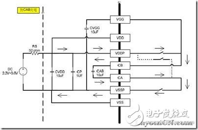
Step 1: Internally, first connect VDDP to CB, VSS to CA, and VDD starts to charge the CAB capacitor, as shown in the following figure:
Step 2: ic internally connects VDDP to CA, VGG connects to CB, and VDD and CAB begin to charge the CVGG capacitor, as shown in the following figure:
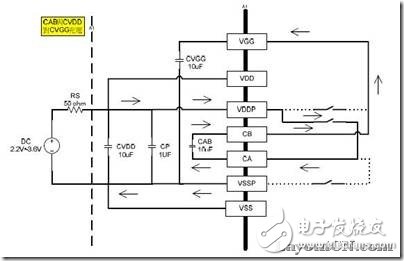
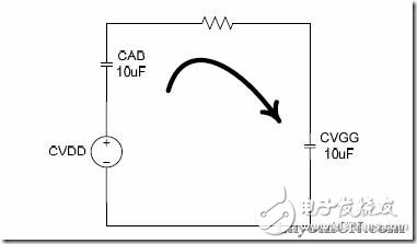
Finally, the voltage on CVGG is actually the voltage of CVDD plus the voltage of CAD. Because there is a process of charging, the different switching frequency of the switch can control the CVGG charging voltage. So in the end we will achieve double pressure!
Motor Three-Phase A.C Induction,Ac Motor Electric Motor Induction Motor,Electric Motor Centrifugal Pump,Electric Motor Centrifugal Switch Gear
Ningbo Zhenhai Rongda Electrical Appliance Co., Ltd. , https://www.centrifugalswitch.com