
Radio frequency identification technology [1] is a non-contact automatic identification technology and is a key technology for building the Internet of Things. According to the frequency band of communication, it can be divided into radio frequency identification systems such as low frequency, high frequency, ultra high frequency and microwave. The UHF readers currently on the market are always unable to get rid of the physical connection with the host computer. The physical connection is mainly used for power supply and data exchange. In some special occasions, these physical connections are very inconvenient, such as UHF reader working outdoors. In this context, based on the UHF protocol ISO/IEC18000-6C, combined with solar charging technology and wireless communication technology, this paper designs a solar wireless UHF reader that can work outdoors and wirelessly communicate with the host computer. The reader is capable of freely switching between USB charging and solar panel charging, charging via USB when there is power to be connected, and charging the lithium battery by solar energy when no power is available, ie outdoors. The Bluetooth to serial port module enables wireless communication between the reader and the host computer. This paper introduces the implementation process of the reader in detail. The main work includes the design of the reader module, the design of the power management module, the software implementation of PIE coding and Miller sequence decoding, and the multi-task operation of μCOS-II.
1 Solar wireless UHF reader hardware circuit design1.1 Overall block diagram design
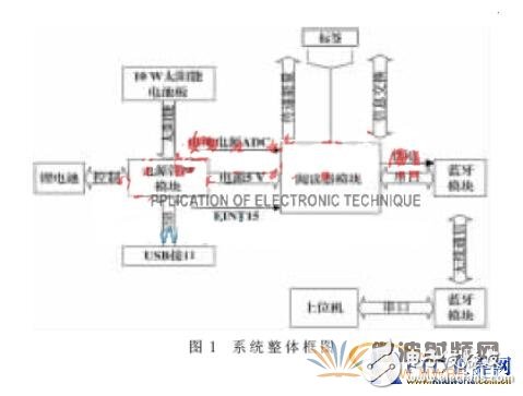
As shown in Figure 1, the overall block diagram of the system hardware consists of three modules: a wireless communication module (Bluetooth module), a reader module, and a power management module. The Bluetooth module realizes wireless communication between the reader and the host computer, receives the command sent by the upper host, and transmits the read tag data to the upper computer. The reader module completes the command PIE encoding and RF signal transmission, tag reflection wave demodulation and Miller sequence decoding, battery voltage check and power-down wake-up. The power management module mainly completes solar energy collection, USB charging, boosting of lithium batteries, and generating battery voltage detection signals.
1.2 Wireless communication module
The wireless communication module designed this time uses the HC-05 serial Bluetooth module [2], which adopts the Bluetooth V2.0 protocol standard. When pairing, the current is 30 mA~40 mA. When the pairing is completed, the current consumption is 2 mA~8 mA, the communication consumes 8 mA, and the communication distance is about 10 m. The Bluetooth module serial port TXD is connected to the reader module RXD, the Bluetooth RXD is connected to the reader module TXD, and connected to the common ground.
1.3 reader module design
The reader module is mainly divided into two parts: baseband data processing and RF signal transmission and reception.
The baseband data processing section mainly performs transmission of commands and decoding of tag return information. The transmitted command uses PIE encoding, and the encoding format of the label return information may be subcarrier FM0 baseband or Miller[3] subcarrier modulation sequence.
The radio frequency section performs modulation of the baseband signal, transmission of the modulated signal, demodulation and amplification of the tag reflection signal. Signal transmission process: The 915 MHz carrier is generated by the RF synthesizer SI4133. The baseband signal is OOK modulated by the ADG198 RF switch device ADG198, and the modulated signal is amplified by RF2162. The power amplifier RF2162 is a heating device, so the RF2162 should be handled well in the hardware layout. The software design should also be protected by RF2162, so that it can be turned off for a while after working for a while. The amplified RF signal is completed by the microstrip line 50?赘 Impedance matching, sent by the antenna.
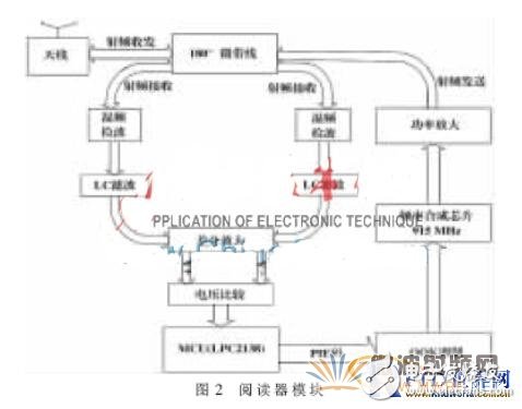
The receiving process of the signal: the receiving circuit adopts the UHF reader demodulation circuit patent [4], the tag reflection signal passes through 50 microstrip lines, and the single-ended signal changes to double-ended signals, as shown in Figure 2, the two-end signals are 180° out of phase. . In the process of receiving signals, there is always carrier transmission (powering the tag), so the received signal and the 915 MHz carrier are split into two channels to achieve mixing and demodulation on the diode, and then LC filtered respectively to become two phase differences of 180°. The differential signal is differentially amplified and finally passed through the voltage comparison chip MAX942 to demodulate the FM0 or Miller sequence returned by the tag.
This design uses the ARM7 chip LPC2138 [5] to process the baseband signal. The generation of the PIE waveform is achieved by adjusting the output waveform period and pulse width of the PWM timer. The FM0 or Miller sequence is captured by capture channel 0 of timer 0 and decoded in conjunction with software.
1.4 Power Management Module Design
According to the design requirements, the reader has a continuous card reading time of about 2 h per day (the rest of the time is standby, the power consumption is lower), the power consumption is 330 mW per hour, and the lithium battery is fully charged for 10 days. Therefore, a lithium battery of 6 800 mAH was selected as the energy storage device. According to the working efficiency of the solar panel and the illumination of the local sunlight, a 10 W solar panel was selected as the solar energy collection device.
The specific requirements of the power management module are: (1) The battery can be charged by USB, or the battery can be charged by the solar panel. When charging with USB, the solar panel charging circuit is cut off. (2) The power management module provides a stable +5 V voltage to the outside, so the lithium battery needs to be boosted and regulated. (3) The MCU needs to monitor the battery power at all times. If the battery power is lower than a certain amount (3 V), the system must be forced to enter the power-down mode. (4) After the battery voltage returns to the normal value (3.9 V), the system is switched from the power-down mode. The circuit diagram of the power management module is shown in Figure 3 and Figure 4.
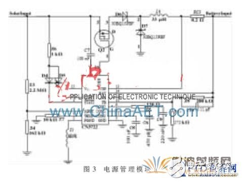
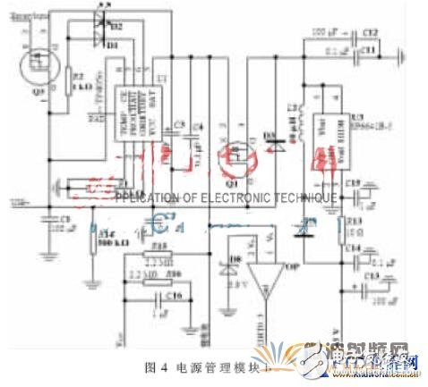
The solar charging circuit is based on CN3722[6]. It uses constant voltage tracking (CVT[7]) to make the most efficient use of solar energy. The magnitude of the charging current during constant current charging is set by the resistor RCS. The constant current charging current is designed to be 1 A. The chip is capable of charging a three-stage charging method for a lithium battery. The USB charging chip uses TP4056. When there is USB charging, the solar charging circuit is disconnected. As shown in Figure 4, PMOS is used. When there is USB charging, Q3: Vg = 5 V, Vs "4.2 V (maximum voltage of lithium battery), Q3 is cut off. Similarly, when USB is charged, Q1 is also turned off, and USB supplies power to the entire system. Due to the unstable battery power supply, a DC-DC boost circuit SP6641B-5 is added to provide a stable 5 V input voltage to the reader module.
The AD0.0 pin of the LPC is connected to the VADC shown in Figure 4, and the pin P0.1 is connected to the OP output EINT0 for real-time battery voltage monitoring. When the voltage is lower than 1.5 V (the lithium battery voltage is divided below 3 V), set P0.1 to receive a high level interrupt and the system enters the power down mode. When the battery voltage is higher than 3.9 V, the output EINT0 of the OP will output a high level, generating an EINT0 interrupt, and the system will wake up from the power down mode. The 3.9 V and 3 V have 0.9 V windows to avoid monitoring errors that cause the system to frequently switch between normal mode and power down mode.
2 Solar wireless UHF reader software design2.1 PIE coding and Miller sequence decoding
Regarding baseband signal processing, the key is the generation of PIE codes and the decoding of Miller sequences.
According to the ISO 18000-6C protocol, Tari is the reference time interval for the interrogator to send a signal (PIE code) to the tag, ie the duration of data 0. PW is the time during which the low level lasts during the Tari time interval. This design chooses Tari to be 6.25 μs and PW to be 3.125? Zi s. Data 1 has a period of 12.5 μs and a PW of 3.125 μs. In order to facilitate the generation of waveforms by PWM, the waveform of data 1 is divided into 6.25?滋s high level plus the waveform of data 0. The PWM5 (pin P0.21) of the LPC2138 acts as a PWM output. Register PWMMR0 sets the PIE sequence period and PWMMR5 sets the position of the falling edge. The values ​​of registers PWMMR0 and PWMMR1 are updated in the PWM interrupt handler to generate the next PIE sequence.
The information transmitted back by the tag complies with the FM0 coding rules: (1) Reverse the phase at each data boundary. (2) Data 0 has a phase reversal in between. Generally, an FM0 code is represented by one subcarrier, but sometimes in order to reduce the signal detection error rate, an FM0 code can be represented by 2, 4 or 8 subcarriers, which is called Miller subcarrier modulation technology. When the reader sends the query command, the number of subcarriers is selected. This design uses M=2. Miller2 code rule: each data sequence is represented by two subcarrier periods, the subcarrier period of data 0 does not phase flip, the subcarrier period of data 1 phase reversal, and the two data 0 boundaries are phase inverted. In this design, the TRext bit in the query is set to 1, so that each time the Miller sequence is returned from the tag, there are 16 leading 0s plus 010111 (preamble), and the preamble sequence is detected to determine whether the reflection has started. data.
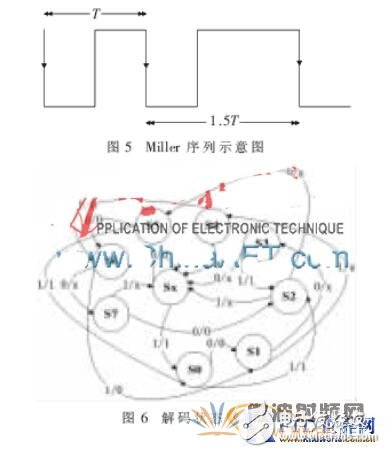
The Miller2 sequence is detected by the capture function and state machine of the LPC2138 timer 0. Studying the Miller2 sequence revealed that the time interval of the falling edge of the Miller2 sequence was only the two cases shown in Figure 5: T or 1.5T (T is Tari = 6.25 μs). The falling edge of the Miller sequence is captured by the capture channel 0 of the timer 0, and the count value of the current timer snapshot is read in the interrupt handler to find the difference from the last count value. The Miller2 sequence of the tag reflection can then be decoded by the state machine shown in FIG. As shown in Figure 6, Sx is the starting state, and the a/b (a: input, b: output) arrow points from the initial state to the secondary state.
The LPC2138 receives the Miller2 sequence pin as P0.2, sets the pin to capture the falling edge, and when the falling edge comes, enters the interrupt handler and reads the value of the capture register CR0. The difference a from the last falling edge is calculated, and the difference is stored in the FIFO (global array), and when there is no falling edge capture, the processor executes the decoding process. This design uses a method of receiving codec. This is because, according to the ISO18000-6C protocol, there is a time limit between commands. If the Miller2 sequence is received and then decoded, the time limit may be destroyed.
2.2 ISO18000-6C command and multitasking implementation
2.2.1 ISO18000-6C command
After completing the PIE code transmission and the tag returning to the Miller2 subcarrier decoding, all the commands specified by ISO18000-6C can be easily implemented. According to the protocol, commands are divided into three categories: select command (select), inventory command (query, queryadjust, ACK, etc.) and access commands (Read, Write, Lock, BlockWrite, BlockErase). According to the format of the command in the agreement, it is implemented separately.
2.2.2 Implementation of multitasking
μCOS-II [8] is a preemptive multitasking operating system kernel, which is very widely used, and it is also very easy to port it to LPC2138. This design requires the reader to have the following features: multi-card access (inventory), single card access, low voltage monitoring. Multi-card access operation means batch card reading; single card access is a read/write, lock and batch access operation of one card; low voltage monitoring realizes the function of detecting battery voltage, when the battery voltage is lower than the lower limit of the threshold voltage, let The reader operates in power-down mode and wakes up the system when the battery voltage returns to the upper threshold voltage.
Create 3 user tasks: MainTask, Tag_Inventory, Tag_Operate, create 2 semaphores: Semp_Invent and Semp_Operate. The MainTask task has the highest priority, set to 5, complete the voltage detection and operation mode selection; the task Tag_Inventory priority is 6, complete multi-card access; the task Tag_Operate priority is 7, complete single card access. After entering the MainTask task, immediately acquire 2 semaphores, use the case statement to achieve task selection, select a task, release the semaphore corresponding to the task, and execute the corresponding task. In the task, first obtain the corresponding semaphore, such as OSSemPend (Semp_Invent, 0, & err), then perform the task, and finally release the semaphore OSSemPost (Semp_Read).
There are two functions in the main task: (1) Check the system voltage. When the voltage is less than 3.0 V, the system enters power-down mode. After that, the system can wake up by an external interrupt only when the system voltage is greater than 3.9 V. (2) Card reading mode selection. When the multi-card access mode is selected, the system saves the EPC of the nearby UHF card and returns to the main task. When the single card access mode is selected, operations such as reading, writing, locking, block reading, and block writing can be performed on a single UHF card.
3 Experimental resultsConnect the solar panel, power management module, reader module, and wireless communication module to consume the power of the lithium battery until the system enters the power-down mode, then place the device in a sunny outdoor area and take proper heat dissipation and waterproof measures. After charging for a period of time, the Bluetooth device of the host computer matches the Bluetooth module of the reader. After the matching is successful, the disk storage command is sent to the reader, and the solar wireless UHF reader can correctly read the EPC of multiple tags (the last 16 bits of the read-only EPC). : FFAB, FF09, FFA9, FF22, FF6C, FF37. The experimental results prove that the design expectations are met.
Copper Dryer Filter
copper filter driers are designed to absorb moisture, acid, and to filter out impurities. Normally be installed as component and replaced as repair part for both domestic and commercial refrigerators, freezers.
This fliter is for air conditioner water tank or fridge, replacing your broken or old one.
Used in two-way circulation refrigeration system tubes
Absorb moisture and acidic harmful substances in the refrigeration system and filter impurities.
This filter dryer is fit for refrigerators (but refrigerator is not including here)
Copper Dryer Filter,Refrigeration Dryer Filter,Refrigerator Water Dryer Filter,Refrigerator Copper Filter Drier
FOSHAN SHUNDE JUNSHENG ELECTRICAL APPLIANCES CO.,LTD. , https://www.junshengcondenser.com