
The standby energy consumption of computer external devices (such as printers, scanners, stereos, etc.) not only increases the daily electricity expenses of consumers, but also wastes power resources. The computer intelligent energy-saving socket of the design utilizes the power on and off of the host to drive other equipment to be turned on or off, so that the standby energy consumption of the interface device is zero, and the radiation generated by the computer and its peripherals can be reduced, thereby achieving energy saving and environmental protection. Efficacy; also has the function of segmented time switch. The smart socket can also be used as a normal socket through function conversion without affecting the use of other devices.
1 Smart socket design
1.1 Hardware structure of smart socket The hardware structure diagram of computer intelligent energy-saving socket is shown in Figure 1. The controller uses AVR mega 48 as the control core. The peripheral circuit is mainly composed of current sampling circuit, analog/digital conversion reference voltage circuit, status display circuit, keyboard input circuit and real-time clock. The current sampling circuit is used for detecting the running state of the computer and the overcurrent protection; the digital/analog conversion reference voltage circuit provides a reference for the sampling of the current; the status display circuit indicates the current running state of the socket; the keyboard input realizes the switching between the ordinary socket and the smart socket, Set the standby critical current value and set the time point of the segmentation switch. The running state of the computer host is detected by the current transformer of the host interface, and the overcurrent protection is detected by another transformer. When the current is greater than the rated current for a certain time, the power of the controlled socket is cut off, and the peripheral is protected. Since the induced current of the transformer is small, the reference voltage is required in the digital-to-analog conversion process. The design uses the bandgap constant voltage source TL431 as the reference voltage for A/D conversion. The standby current of different computer mainframes may be different, so the standby current can be sampled by the external keyboard as a threshold, and the socket can be set as a normal socket; the RTC clock is composed of PCF8563.

This article refers to the address: http://
1.2 AVR Microcontroller The AVR microprocessor is an 8-bit embedded RISC processor from Atmel. It has the advantages of high performance, high confidentiality, low power consumption, Harvard structure with independent access to program memory and data memory, and code execution efficiency. high. The system uses a mega 48v processor with 4 KB of on-chip programmable FLASH program memory; 512 B of E2PROM and 512B RAM; and an on-chip watchdog integrated; 8 10-bit ADCs; 3 programmable PWM outputs With online system programming, rich on-chip resources, high integration, easy to use. The AVR mega48V makes it easy to set external input parameters, current detection, and indication of operating status.
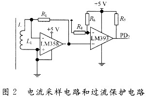
1.3 Current Sampling Circuit This design uses current-type current transformer to sample AC current, one-way sampling host interface current realizes switch control, and the other sampling controlled interface current realizes over-current protection (see Figure 2). The output signal of the current transformer is sampled by mega 48 after IV conversion, and the effective value of the current can be calculated according to the ratio coefficient of the transformer. After the output voltage of the IV conversion passes through the comparator, if the overcurrent limit is reached (set to 10 A), the external interrupt is triggered, and the interrupt program is processed to determine whether the overcurrent value is reached and the overcurrent protection action is performed.
1.4 Power Circuit The operating voltage of the MCU and the coil side voltage of the relay are 5 V DC voltage. Considering the cost and space factor, it is generated by means of RC. As shown in Figure 3.
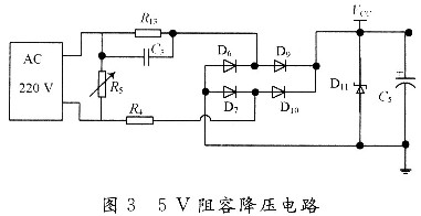
In Figure 3: C3 is the CBB step-down capacitor; _R13 provides a discharge loop for C3 after the power is turned off; R4 is the current-limiting resistor; after full-wave rectification, D11 clamps the voltage at 5.1V. The capacitive reactance XC of C3 in the circuit is: XC=(1/2)πfc, current. In order to meet the current requirement of the relay when it is connected, the value of C3 is 1μF, and the maximum current can reach more than 100 mA. Since it is a non-isolated power supply, the zero potential cannot be connected to the ground during use.
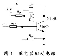
1.5 Relay drive circuit The control of the continuity of the socket is controlled by the relay. The design uses a relay with a coil side voltage of 5V and drives the relay with the S8050. The mega 48 has a strong I/O drive capability, R17 acts as a current limiter; the pull-down resistor R18 prevents the relay from malfunctioning; D12 provides a discharge loop when the relay is open. As shown in Figure 4.
1.6 Keyboard circuit adopts the input mode of single button, which is used to set the function conversion of ordinary socket and smart socket and the time setting when timing switch is needed. During the running of the program, it is detected by the timer interrupt whether there is a button press. When the function key is pressed for less than 10s, it enters the time switch mode, and the time switch is set by the addition and subtraction buttons; when the function key is pressed for more than 10 s, it is switched to the normal socket, if it needs to be switched to the smart socket, then Do the same. The set parameters and modes are saved in the E2PROM of the mega 48.
1.7 Status Display and Alarm Circuit This design uses the status information of the LCDl602 liquid crystal display system, including whether to use intelligent control, host running status, and controlled port status. LCDl602 uses a 7-wire drive method with a 1 kΩ resistor to ground for adjusting the LCD contrast. The display data and instructions are written by DB4 to DB7 of LCDl602. At the same time, it has the function of sound and light alarm. When there is overcurrent or the timing off time is reached, the corresponding LED flashes and the buzzer alarms, and the corresponding action is performed.
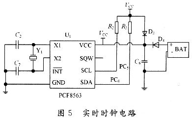
1.8 Real Time Clock Circuit The real time clock circuit provides accurate time for the time switch. A CR2025 Ni-MH button battery was used as a backup battery for the PCF8563 (see Figure 5).
2 The software design of the smart socket main program mainly completes the initialization of the I/O, the timer, reads out the system parameters stored in the E2PROM, and enters the corresponding processing program according to the mode setting. The socket can operate in three modes: intelligent timing mode, smart energy saving mode and normal mode. The mode switching is selected by the mode button. The measurement of the parameters is mainly done by the interrupt service routine at regular intervals. Figure 6 is the main program flow chart.
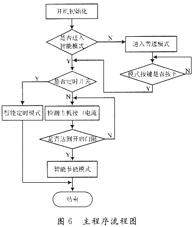
Since different computer standby currents are not the same size, the host's standby current needs to be sampled before use. First, the host enters the standby mode, and the current at this time is sampled after entering the interrupt through the mode button, and stored in the E2PROM.
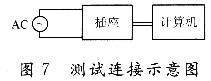
3 Smart socket test The designed socket is connected and tested according to the method of Figure 7. It is tested with P4 dual-core computer and 17-inch display. The standby power consumption of the display is 5W and the standby current is about 25mA. After entering the standby state, press the sampling button on the socket to store the standby current sample of the computer into the E2PROM. The test result shows that when the computer enters the standby state, the socket can effectively cut off the power of the display.
4 Conclusion The intelligent energy-saving socket designed in this paper has intelligent energy-saving and time-switching functions, and can also be used as a common socket. After testing, the system shows a good control effect, not only reduces the standby power of computer peripherals to zero, but also plays a role in protecting peripherals. It has certain social benefits and wide promotion value in energy saving and emission reduction.
Control cable is a kind of cable. It is used for control and monitoring circuits and protection circuits with AC rated voltage of 450V/750V and below. Shielded control cables are widely used in power plants and power stations due to their good shielding performance. They are intended to be laid indoors, in cable trenches, in pipelines, directly buried, in shafts and other fixed places that can withstand greater mechanical tension.
Feature
1. DC rated current Uo/U is 450/750V2. The maximum allowable long-term operating temperature of the cable electrical conductor is 70 ℃.
3 The working temperature during cable laying shall not be lower than 0 ℃. If the natural environment temperature is lower than 0 ℃, the cable shall be heated.
4 The strongly recommended allowable bending radius of cable is below:
The unarmoured cable shall not be less than 6 times of the cable diameter;
Armored cable or copper foil shielded cable shall not be less than 12 times of cable diameter;
The shielded Flexible Cable shall not be less than 6 times of the cable diameter.
5 Productive cable model 2-61 cores
6 Control cables are generally laid in rooms, cable trenches, pipelines and other fixed sites.
Copper Conductor PVC Jacket Control Cable,Armoured Control Cable,Multi Core Control Cable,Sheathed Control Cable
Ruitian Cable CO.,LTD. , https://www.rtpowercable.com