
Experiment 5 Differential amplifier circuit experiment
1. The purpose of the experiment
1. Master the test method of differential amplifier circuit principle and main technical indicators
2. Familiar with the performance difference between the basic differential amplifier circuit and the differential amplifier circuit with a mirrored constant current source, and clear measures to improve performance.
2. Experimental equipment
1. One oscilloscope. 2. One signal source. 3. One millivolt meter. 4. One DC power supply. 5. One digital multimeter. 6. Several resistors, capacitors and crystal transistors.
3. Experimental principle
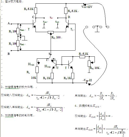
1. Differential amplifier circuit
5. Replace Re with a constant current source:
Due to the AC equivalent resistance of the constant current source >> Re
4. Experimental content:
1. Connect the experimental circuit according to the schematic diagram. Note: Power connection
2. Measurement of static operating point.
3. Measurement of differential mode voltage magnification. When measuring VOPP, since VO1PP and VO1PP are inverted, the oscilloscope CH1 is superimposed and CH2 is inverted.
4. Measurement of common mode voltage magnification. When measuring VOPP, since VO1PP and VO1PP are in phase, the oscilloscope CH1 is superimposed, and CH2 does not need to be inverted.
5. Measurement of differential mode voltage magnification with constant current source. Adjust Rp2 to make Vc1 and Vc2 equal to the values ​​in Table 1.
6. Measurement of common mode voltage magnification with constant current source.
Circuit form | Input signal type | VIPP (f = 1KHz) | VO1PP / V | VO2PP / V | VOPP / V | Avd1 | Avd2 | Avc2 | |
Basic form | Differential mode | 100mV | / | / | |||||
Common mode | 5V | / | / | ||||||
Constant current source form | Differential mode | 100mV | / | / | |||||
Common mode | 5V | / | / |
V. Reporting requirements (refer to textbook requirements)
1. Organize the data and process it. 2. According to the test results, explain the differences and causes of the circuit performance of the two differential amplifier circuits. 3. Answer the thinking questions.
6. Preview content p79-83
Semiconductor Fuse And Ferrite
Fuse refers to an electric appliance that, when the current exceeds the specified value, melts the fuse and disconnects the circuit with the heat generated by itself.When the current exceeds the specified value for a period of time, the fuse melts and disconnects the circuit with the heat generated by the fuse itself.A current protector made from this principle.The fuse is widely used in high and low voltage power distribution system and control system as well as power equipment.
Ferrite is a metal oxide with ferrous magnetism.As far as electrical properties are concerned, the resistivity of ferrite is much larger than that of single metal or alloy magnetic materials, and it has higher dielectric properties.Ferrite magnetic energy also shows high permeability at high frequencies.As a result, ferrite has become a non-metallic magnetic material widely used in the field of high frequency and weak current.Due to the low ferrite magnetic energy stored in the unit volume, saturated magnetic induction strength (Bs) and low (usually only pure iron 1/3 ~ 1/5), and thus limits its higher requirements in the low-frequency magnetic energy density in the field of high voltage and high power applications.
Semiconductor Fuse, Fuse Cutout, Protection Fuse, Square Fuse, Fuse Link, Ceramic Fuse, Fuse Box, Fuse Resistors
YANGZHOU POSITIONING TECH CO., LTD. , https://www.pst-thyristor.com