
Over the past few years, small color LCD displays have been integrated into a wider and wider range of products. The color display was once regarded as a luxury configuration for mobile phones, but now, even in entry-level phones, color screens have become a standard. Fortunately, the economic scale of the mobile phone industry (the global annual mobile phone shipments are close to 1 billion units) has reduced the cost of LCD color displays and integrated them in whether it is portable medical equipment, universal entertainment remote control, digital photo frame / image viewing Devices, educational toys, or the latest WiFi-enabled VoIP cordless phones and other products are all attractive.
The color LCD display requires a white backlight so that users can watch normally in any lighting environment. This backlight subsystem includes a high-brightness white light-emitting diode (LED) array, a diffuser (diffuser) to diffuse light, and a backlight driver to regulate the available power to a constant current to drive the LED. A 1- to 1.5-inch display may contain 2 to 4 LEDs, while a 3.5-inch display may easily contain 6 to 10 LEDs. For LEDs, the light output is proportional to the current, and because the LED has a very steep current-voltage (IV) curve, it is very important to closely match the current flowing through the LED, so as to ensure a balanced backlight, because the LED is usually distributed in One side of the LCD display. In addition, software control is also required to allow users to adjust the brightness and compensate for the surrounding lighting environment. Depending on the current flowing through the LED, the color point of the LED may drift. Therefore, it is common to set the LED current to a fixed value and pulse-width-modulate the LED to reduce the average light output. There are a number of factors that need to be considered to integrate a small color LCD display in the design of a handheld product and then achieve an appropriate balance of cost, performance, and battery life.
Battery-powered products require optimized LED driver circuit architectures that address multiple challenges that coexist, such as space constraints, the need for high energy efficiency, and battery voltage changes—both may be higher or lower than the LED's forward voltage. There are two commonly used topologies, namely the charge pump architecture / constant current source architecture with LEDs in parallel configuration and the inductive boost architecture with LEDs in series configuration. Both schemes have trade-offs that need to be considered. For example, the boost architecture can ensure that all LEDs pass the same amount of current but need to use an inductor for energy conversion, while the charge pump architecture uses small capacitors for energy conversion, but all LEDs are connected in parallel. Arranged too closely so that current matching becomes a difficult problem faced by balanced backlights. Figure 1 shows examples of these two architectures.

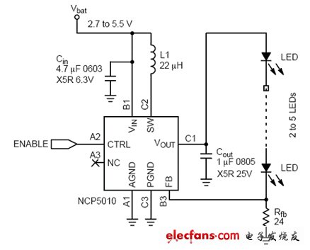
Figure 1: Circuit diagram of charge pump and inductive LED driver.
The following points should be done during design
1. Evaluate the approximate usage time of the display
When choosing a white LED driver, you need to consider the frequency of use of the display. If the display will be viewed for a long period of time with backlight, it is very important to have a highly efficient converter for battery life. Larger displays require more LEDs, and applications with longer display lifetimes will benefit from the more energy-efficient boost topology. Conversely, if the display is only used for short-time backlighting, efficiency may not be a critical design parameter.
2. Carefully consider LED selection
LED technology continues to improve rapidly. Manufacturers are using new materials, manufacturing technologies, and LED designs to release greater light output for currents of the same size. As a result, displays that required 4 LEDs for backlighting a few years ago are now 2 LEDs may be used to achieve the same backlight brightness. Not only that, the large 4 to 7-inch display screens that used to be backlit with cold cathode fluorescent lamps (CCFL) in the past are now turning to LEDs for backlighting. In addition, the forward voltage of LEDs is tending to be lower. Therefore, not only the driver efficiency on the curve of the driver manufacturer's data sheet needs to be considered, but also needs to be considered based on the evaluation of the driver using the selected LED. Table 1 lists some important specifications of several LEDs, showing the difference in forward voltage and luminous brightness of these LEDs. It should be noted that the change in the forward voltage range is large, which means that the efficiency of the driver should be evaluated using the limit value of the LED specification.
3. Pay attention to wiring
Even if each LED is driven with a very low current of 10 to 20 mA, the peak current flowing through the converter is significantly higher. This is especially true for inductor topologies, because the peak switching current may be 10 to 20 times the average LED current. Therefore, it is necessary to use appropriate low-loss wiring technology. For the charge pump topology, the capacitor should be placed adjacent to the driver to minimize the loop area to avoid radiating switching noise. For inductive boost converters, the input and output capacitors and electrical induction are located adjacent to the driver. In addition, the current setting resistor (Rfb) should be directly connected to the ground of the chip, because the error between the internal reference and the detected voltage will directly affect the LED current accuracy.
4. Test your test product in a real environment
Consider the performance of the display screen under high-brightness lighting conditions from outside, and ensure that the software dimming control has sufficient dynamic range so that the display screen can be fully dimmed under the expected lighting environment.
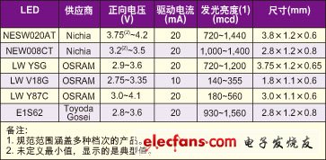
Table: Characteristic parameters of several different LEDs.
Should pay attention to avoid the following problems
1. Forgetting to consider boundaries and failure modes
Errors always occur. If the LED is open or shorted to ground, how should the driver handle this problem? For an inductive boost driver, if the LED string is open, the output will surge, because the constant current will charge the output capacitor, which requires overvoltage protection, but this function may or may not be integrated in the driver. This may become a problem in factory testing, because the display may not be installed in some test steps. In addition, it is also important to evaluate the surge conditions when the product is turned on, because the large current consumption during this period may reduce the battery voltage below the minimum operating threshold. Soft start and / or software sequencing of different circuit modules can minimize this problem.
2. Staring at peak efficiency only
Since the user can adjust the backlight brightness, it is necessary to consider the driver efficiency of the display backlight is expected to be in most working hours. When evaluating the efficiency of a driver, you need to consider the expected operating conditions of the LED, the battery voltage range, and the forward voltage change. Inductive drivers have better peak efficiency and greater tolerance for input and output voltage changes.
3. Ignore external component selection
In all design cases, consideration should be given to using low equivalent series resistance (ESR) X5R or X7R ceramic capacitors to minimize losses. Also in the inductive case, (if external) the forward voltage drop of the Schottky rectifier and the ESR of the inductor affect the efficiency. For example, when using an inductor with 0.3Ω ESR to drive 5 LEDs in series at 20mA, the efficiency will be 5% higher than that with 1.3Ω ESR. Of course, this is not without cost, because the lower the ESR of the inductor, the larger the size corresponding to the same inductance value. Fortunately, there are also many new small-size inductors that allow LED drivers to be placed under the display.
The pin refers to the connection between the internal circuit of the integrated circuit (chip) and the peripheral circuit, and the pin constitutes the interface of the chip. According to the function, the pins of AT89S52 can be divided into four categories: main power supply, external crystal oscillator or oscillator, multi-function I/O port, and control, strobe and reset.
Terminal Pins,Terminal Hardware Pin,High Precision Terminal Pins,Terminal Pins For Pcb
Sichuan Xinlian electronic science and technology Company , https://www.sztmlchs.com