
There are many ways to implement fractional frequency synthesizers, such as Pulse swallowing, Pulse interpolatoin, Wheately random jittering, and Σ-Δ modulation [1]. The Σ-Δ modulation architecture is characterized by its excellent phase noise index and full digitization. The mainstream of fractional frequency synthesizers. This paper aims to analyze the influence of Σ-Δ quantization noise on the phase noise and spurs of the fractional frequency synthesizer, and find a sigma-delta modulator suitable for the fractional frequency synthesizer.
1 phase noise
Based on the phase-locked loop closed-loop loop, the fractional frequency synthesizer is realized, and a linear mathematical model is established to analyze the phase noise source and transfer function.
1.1 Phase noise model
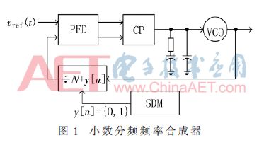
Rohde has stated [2] that every component of the PLL produces noise. The main phase noise sources of the fractional frequency synthesizer are reference clock phase noise θref(t), PFD phase noise θPFD(t), VCO phase noise θVCO(t), frequency divider phase noise θdiv(t), Σ-Δ quantization. noise.
The synthesizer based on the phase-locked loop fractional frequency is shown in Figure 1.
Define Ï„n as the rising edge of the nth reference clock, then: [3]
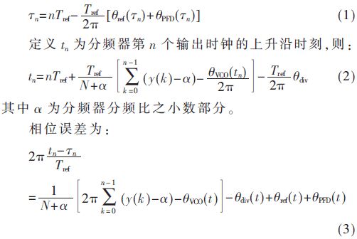
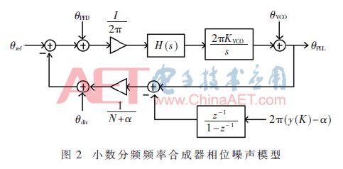
From the phase error formula and Fig. 1, the phase noise linear model of the Σ-Δ fractional frequency synthesizer shown in Fig. 2 can be derived.
1.2 Phase noise analysis
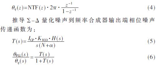
The transfer function of the phase noise source to the output of the Σ-Δ fractional frequency synthesizer is the low-pass filter transfer function except that the VCO phase noise transfer function is a high-pass filter transfer function. This paper focuses on the analysis of the effect of Σ-Δ quantization noise on the output phase noise.
In Fig. 2 (y(k) - α) is a Σ-Δ quantization noise q(t) whose Z-domain transfer function NTF(z) = (1-z-1)L[4]. The phase noise injected into the PLL by quantization noise is:
1.2.1 Effect of Σ-Δ quantizer order on phase noise
MATLAB plots different Σ-Δ quantizer orders and quantizes the frequency domain response of the PLL output phase noise caused by noise, as shown in Figure 3. The curve "." is the phase noise injected into the frequency synthesizer by the second-order Σ-Δ quantizer 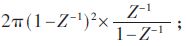
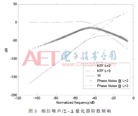
It can be seen that the higher the order of the Σ-Δ quantizer, the lower the in-band phase noise of the fractional frequency synthesizer.
1.2.2 Effect of Loop Bandwidth on Phase Noise
Figure 4 shows a 3rd order Σ-Δ quantizer with a phase noise spectrum of the fractional frequency synthesizer under different PLL loop filter bandwidths. The curve "." is the third-order Σ-Δ quantizer phase noise; the curve ".-" is the phase noise transfer function of the frequency synthesizer with bandwidth of 10 kHz and 1 MHz respectively; the solid line is the third-order 带宽 of the bandwidth of 10 kHz and 1 MHz, respectively. -Δ frequency synthesizer phase noise.
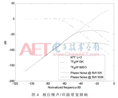
It can be seen that the smaller the loop bandwidth, the lower the phase noise caused by Σ-Δ quantization.
2 phase noise optimization
Through the 1.2.1 analysis, the high-order sigma-delta quantizer can push the quantization noise to the high frequency, so that the in-band quantization noise is reduced, and the frequency synthesizer output phase noise is also reduced.
The MASH high-order Σ-Δ quantizer consisting of a first-order modulator is unconditionally stable, but the problem with the MASH Σ-Δ quantizer is that its output is multi-bit, the frequency synthesizer's divider design is complex, and the frequency division ratio Switching between multiple modes introduces high frequency jitter to the output of the phase detector.
The high-order single-loop Σ-Δ quantizer has stability problems. In order for the high-order single-loop Σ-Δ quantizer to work stably, its noise transfer function gain needs to be satisfied [5]:

The feedforward path is introduced through a high-order loop, and the NTF gain is changed to make it work stably. However, the disadvantage is that NTF's suppression of quantization noise is lower than that of ideal NTF(z)=(1-z-1)L. In this paper, it is proposed that the signal is added to the high-frequency zero point before the input Σ-Δ quantizer, so that the fractional frequency synthesizer with built-in second-order sigma-delta quantizer obtains phase noise comparable to that of the high-order sigma-delta frequency synthesizer. index. Phase noise optimization is shown in Figure 5.
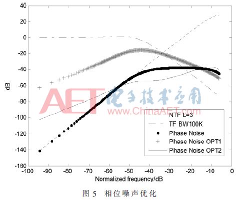
In Fig. 5, the curve "--" is the third-order Σ-Δ quantizer phase noise; the curve ".-" phase noise transfer function; the curve "+" is the second-order Σ-Δ frequency synthesizer phase noise; the curve "." It is the third-order sigma-delta frequency synthesizer phase noise; the solid line is the second-order sigma-delta frequency synthesizer phase noise after the high-order zero is inserted. Obviously, after the input signal is inserted into the high-frequency zero point, the second-order sigma-delta frequency synthesizer can obtain high-order sigma-delta quantization frequency synthesizer performance.
Another way to optimize phase noise is to reduce the frequency synthesizer loop bandwidth, as shown in the 1.2.2 analysis. However, in order to suppress the VCO phase noise, it is necessary to increase the frequency synthesizer bandwidth [6]. In the design, compromise optimization is needed to find the optimal bandwidth.
It should be noted that after the Σ-Δ frequency synthesizer is locked, the output frequency of the Σ-Δ quantizer is equal to the reference clock frequency, the reference clock frequency is increased, the quantizer operating frequency is also increased, and the quantization noise can be pushed to a higher frequency, and the signal is input. The in-band phase noise is lower, and there is no need to reduce the phase noise by driving down the frequency synthesizer bandwidth, which increases the bandwidth of the sigma-delta frequency synthesizer.
3 stray
The spur generation mechanism of Σ-Δ frequency synthesizer is analyzed. From the perspective of optimizing Σ-Δ modulator, the spur suppression measures are proposed.
3.1 Spurious analysis
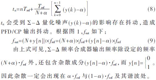
The Σ-Δ frequency synthesizer dynamically switches due to the feedback branch divider frequency division ratio, and the rising edge of the feedback signal is:
In addition, the Σ-Δ quantizer has insufficient number of bits, which causes the quantizer to saturate, causing large spurs. At the same time, the quantizer saturation will also deteriorate the noise transfer function NTF, and the high-frequency quantization noise will enter the signal band.
The third-order Σ-Δ quantizer time domain expression is:

The normalized quantization noise |q[n]|≤0.5 gives |y[n]|≤|a|+4.
At least 3 bits are required to represent y[n], and the quantizer is not saturated [7].
3.2 spur suppression
Optimize the sigma-delta quantizer design to suppress spurs.
In order to suppress the inherent spurs of the sigma-delta frequency synthesizer, a very low energy white noise can be superimposed on the input signal of the sigma-delta quantizer [8]. The output frequency error portion after superimposing white noise can be expressed as (y[n]-α+qwhite)×fref. The presence of white noise makes the frequency error portion no longer fixed to the spurs occurring at α × fref and (1 - α) × fref and its harmonics.
To reduce the phase noise of the sigma-delta frequency synthesizer, a high order sigma-delta quantizer is required. It can be seen from Section 3.1 that the high-order sigma-delta quantizer requires a high number of quantizers to cause the quantizer to saturate and produce spurs. However, the number of quantizers is high, y[n] has a wide range of values, and the output frequency spurs (y[n]-α)×fref will generate more harmonics, which will result in a larger instantaneous phase difference. The phaser has a high linearity [9]. From the perspective of suppressing spurs, the order of the Σ-Δ quantizer should not be high. For a second-order Σ-Δ quantizer, the time domain expression is:

The normalized quantization noise |q[n]|≤0.5 gives |y[n]|≤|a|+2. y[n] can be represented by 2 bits, and the quantizer will not be saturated. The second-order sigma-delta frequency synthesizer has a small spurious component compared to the high-order sigma-delta frequency synthesizer.
4 chip implementation
The 1.575 GHz PLL IP was designed based on the SMIC 0.13 μm RF process. The fractional frequency division of the PLL is dynamically switched by the output of the digital second-order sigma-delta quantizer to the PLL feedback path division ratio, which satisfies the GPS clock ultra-low phase noise/spurness index. The IP has been mass-produced on the GPS receiver chip. Get -150 dBm receive sensitivity.
5 Conclusion
In this paper, the influence of Σ-Δ quantizer on phase noise and spurs of fractional frequency synthesizer is analyzed, and the linear mathematical model of fractional frequency synthesizer is established. The reliability of theoretical analysis is verified by MATLAB. At the same time, an optimized Σ-Δ quantizer measure is proposed to reduce the phase noise and spurs of the fractional frequency synthesizer. In this paper, the second-order sigma-delta quantizer with the input signal pre-inserted into the high-frequency zero point and superimposed with low-energy white noise is suitable for the sigma-delta frequency synthesizer. The frequency synthesizer bandwidth can be increased by increasing the sigma-delta resident quantizer operating frequency.
Dongguan Yijia Optoelectronics Co., Ltd. , https://www.everbestlcdlcms.com