
With the development of modern electronic technology and computer technology, various buses have emerged. The architecture of the microcomputer has also undergone significant changes. For example, the increase in CPU speed, the emergence of multi-processor architectures, and the widespread use of cache memories require high-speed buses to transfer data, resulting in a multi-bus architecture. In the multi-bus structure, the PCI bus dominates various bus standards due to its high speed, high reliability, low cost and good compatibility.
PCI bus structureAs a local bus of the processor system, the PCI bus is a component of the processor system. It describes the structure of the PCI bus and cannot leave the processor system. In a processor system, the module associated with the PCI bus is shown in Figure 1-1.
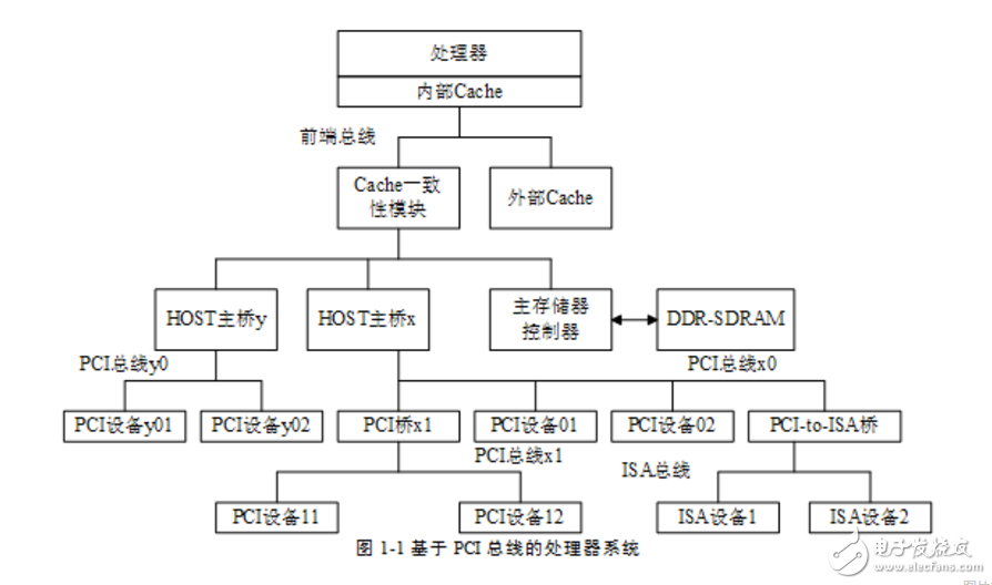
As shown in Figure 1-1, in a processor system, the modules associated with the PCI bus include a HOST host bridge, a PCI bus, a PCI bridge, and a PCI device. The PCI bus is introduced by the HOST main bridge and the PCI bridge. The HOST main bridge and the main memory controller are on the same level bus. The PCI device can conveniently access the main memory through the HOST main bridge, that is, perform DMA operation.
It is worth noting that the DMA operation of the PCI device needs to be consistent with the Cache of the processor system. When the PCI device accesses the main memory through the HOST host bridge, the Cache coherency module will perform address monitoring and change the Cache according to the result of the monitoring. status.
In some simple processor systems, PCI bridges may not be included. In this case, all PCI devices are connected to the PCI bus that is introduced by the HOST host bridge. In addition, some processor systems may contain multiple HOST host bridges. The processor system shown in Figure 1-1 contains the HOST host bridge x and the HOST host bridge Y.
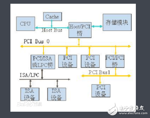
The PCI bus is a tree structure and is independent of the CPU bus and can operate in parallel with the CPU bus. PCI devices and PCI bridges can be attached to the PCI bus. Only one PCI master device is allowed on the PCI bus. The other are PCI slave devices, and the read and write operations can only be performed between the master and slave devices. The data exchange needs to be relayed through the master device. The PCI bus structure is shown in the figure below.
In the processor system, there are two concepts of PCI bus and PCI bus tree. These two concepts are not the same. There may be multiple PCI buses in a PCI bus tree, and the blood-related PCI bus constitutes a PCI bus tree. The PCI bus is managed by the HOST main bridge or PCI bridge and is used to connect various devices such as sound cards, network cards and IDE interface cards. In a processor system, the PCI bus can be extended by a PCI bridge and a multi-level PCI bus with a blood relationship can be formed to form a PCI bus tree structure. There are several HOST host bridges in the processor system, and there are several such PCI bus trees, and each PCI bus tree corresponds to one PCI bus domain.
The PCI bus directly connected to the HOST host bridge is usually named PCI bus 0. Consider that there may be multiple master bridges in a single processor system. The PCI bus replaced the earlier ISA bus. Of course, with the AGP bus dedicated to the graphics card behind the PCI bus, compared with the current PCI Express bus, the function is not so powerful, but PCI can be used from 1992 to the present, indicating that he has many advantages, such as plug and play ( Plug and Play), interrupt sharing, and more. Here we give an in-depth introduction to the PCI bus.
From the data width point of view, the PCI bus has 32bit and 64bit points; from the bus speed, there are 33MHz and 66MHz. Currently popular is 32bit @ 33MHz, and 64bit systems are gaining popularity. The improved PCI system, PCI-X, can reach up to 64bit @ 133MHz, which can get more than 1GB/s data transfer rate. If there is no special explanation, the following discussion takes 32bit @ 33MHz as an example.
Unlike the ISA bus, the address bus and data bus of the PCI bus are time-multiplexed. The advantage of this is that on the one hand, the number of pins of the connector can be saved, and on the other hand, the burst data transmission can be realized. When doing data transmission, one PCI device is the initiator (master, IniTIator or Master), and the other PCI device is the target (slave, Target or Slave). The generation and control of all timings on the bus is initiated by the Master. The PCI bus can only be transmitted by a pair of devices at the same time. This requires an arbitration mechanism (Arbiter) to determine who has the authority to get the mastership of the bus.
When the PCI bus is operating, the initiator (Master) first sets REQ#. When the Arbiter is granted (GNT#), FRAME# is set low and the Slave address is placed on the AD bus. /BE# places a command signal indicating the next transfer type. All devices on the PCI bus need to decode this address. The selected device should set DEVSEL# to declare that it is selected. Then when both IRDY# and TRDY# are deasserted, data can be transferred. Before the Master data transfer ends, FRAME# is set high to indicate that only the last set of data is to be transmitted, and IRDY# is released after the data is transmitted to release the bus control.
Here we can see that the PCI bus transmission is very efficient. After issuing a set of addresses, the data can be sent continuously under ideal conditions with a peak rate of 132MB/s. In fact, the current popular 33M@32bit North Bridge chip can generally achieve 100MB/s continuous transmission.
Custom Wire Harness Assembly
- Electrified dimensional build boards with 100% continuity test
- Capabilities to test for fuse,diode,resistor, and relay presence
- Mating test fixtures for lower production wire harnesses
- Ability to free hand build harnesses for prototypes and design validation
- Separate layout boards for addition of fir tree clips, rosebuds, clamps,and labels after coverings added
- Capabilities to add board interlocks and test markings to harness as needed
Custom Wiring Harness,Wiring Harness,Cable Assemblies,Wire Harness,Wire Harness Assembly Manufacturer
ETOP WIREHARNESS LIMITED , https://www.oemwireharness.com