
When it comes to mobile robots, everyone's first impression may be service robots. Actually, driverless cars, autonomous drones, and so on all belong to the category of mobile robots. They can walk and fly freely in a specific environment like humans, relying on their respective functions such as navigation, path planning, and obstacle avoidance, while visual algorithms are key technologies for implementing these functions.
If you dismantle the vision algorithm of the mobile robot, you will find that acquiring depth information, positioning navigation, and barriers are all based on different visual algorithms. In this issue, we will talk about several different but necessary Indispensable visual algorithm components.
Sharing guests: Chen Zichong, senior architect and algorithm leader of the Segway & Ninebot robotics business. He graduated from the Electronic Engineering Department of Tsinghua University and completed a complete set of software and hardware implementation of satellite beacons based on DSP. He was awarded an excellent paper for undergraduate students. After receiving a doctoral degree at the Swiss Federal Institute of Technology, his doctoral thesis won the National Outstanding Self-financed Student Award. After returning to China, he joined Huawei Media Labs to lead the team to successfully develop real-time binocular vision algorithms for Huawei mobile phones. In 2015, Chen Zichong joined the Segway Robot Project and devoted himself to the development of visual perception algorithms such as robot navigation. The Segway Robot project was released at the International Consumer Electronics Show (CES) keynote in January 2016. It was followed by many international media including CNN, Forbes, TechCrunch, Wired, and was named one of the CES best robots.
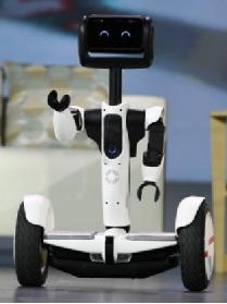
The Segway Robot is a wheeled mobile robot. Its chassis is a balance car with more than 400 patented technologies. In addition, it has an Intel Atom processor, RealSense depth camera and a variety of sensors.
The types of vision algorithms for mobile robotsQ: What navigation algorithms are needed to support navigation, path planning, and obstacle avoidance?
When talking about mobile robots, the need many people think of might be like this: “Hey, can you go over there to help me get a hot latte?†This task, which sounds very simple to ordinary people, is in the robot world. However, it is full of challenges. In order to complete this task, the robot first needs to load the map of the surrounding environment, precisely locate its own position in the map, and then according to the map to carry out path planning control to complete the movement.
In the process of moving, the robot also needs to avoid obstacles in real-time according to the three-dimensional depth information of the scene environment until reaching the final target point. In the course of thinking of this series of robots, it can be decomposed into the following parts of the visual algorithm:
1. Depth information extraction
2. Visual navigation
3. Visual obstacle avoidance
We will describe these algorithms in detail later, and the basis of these algorithms is the visual sensor on the robot head.
The basis of visual algorithms: sensorsQ: Can the camera on the smartphone be the robot's eyes?
The basis of all visual algorithms is ultimately the visual sensor on the robot's head. It is like the human's eyes and the night vision are very good animals, the perceived ability to perform is completely different. In the same way, an eyed animal has less ability to sense the world than two eyes. The smart phone camera in each person's hands can actually be used as the robot's eyes. The very popular Pokeman Go game uses computer vision technology to achieve AR effects.
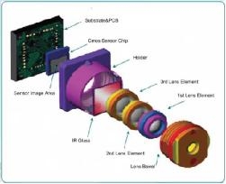
Picture source: ulightech
As shown in the picture above, a camera module in a smart phone contains the following important components: a lens, an IR filter, and a CMOS sensor. The lens is generally composed of several lenses. After complicated optical design, inexpensive camera materials can now be used to make the camera with excellent imaging quality.
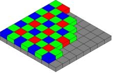
Image source: wikipedia
Above the CMOS sensor is a color filter called the Bayer tricolor filter array. Each different color filter can pass a specific wavelength of the light wave, and corresponding to the CMOS light-sensing device can obtain different light intensities at different positions. If the resolution of the CMOS sensor is 4000x3000, in order to get the same resolution RGB color image, a computational camera algorithm called demosaicing is needed to solve the 2x2 RGB information from the 2x1, 1x1, and red 2x2 grids.

Image Source: thorlabs
Picture source: alibaba
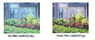
The general CMOS photosensitivity characteristics are transparent to infrared light except for the red, green, and blue colors. Therefore, IR filters are added to the optical path to remove the interference of infrared light from the sun's rays to the CMOS. With the filter, the contrast of the image is usually improved significantly.
Q: What sensor will be used in computer vision?
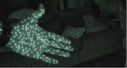
In addition to RGB cameras, there are other kinds of special cameras commonly used in computer vision. For example, there is a camera filter that only allows infrared light. Because the human eye does not normally see infrared light, an active infrared light source can be added near the camera for applications such as distance measurement.
Picture source: dailyvsvidz
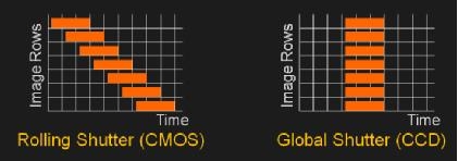
In addition, most of the cameras we use are electronically exposed in the form of a rolling shutter. As shown on the left side of the figure, in order to reduce the cost of electronic devices, the exposure is usually performed line by line, which will inevitably cause objects to move quickly. The image acquired by the camera will deform. In order to avoid the influence of such deformations on the visual algorithms based on the calculation of the three-dimensional geometry (for example, VSLAM), the use of a camera with a global shutter is particularly important.
Picture source: ericmojo
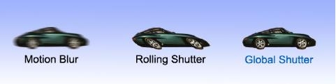
Image Source:teledynedalsa
Depth cameras are the sensors needed in another category of visual algorithms and can be divided into the following categories:
1. TOF sensor (eg Kinect 2 generation), similar to insect compound eyes. High cost, outdoor use.
2. Structural light sensor (such as Kinect 1 generation), trigonometric positioning principle, cost, can not be used outdoors.
3. Binocular vision (eg Intel Realsense R200), active or passive illumination, IR or visible light. Low cost, outdoor use.
Algorithm 1: depth information extractionQ: How does the depth camera identify the depth information of an object?
In a nutshell, the principle is to use two parallel cameras to triangulate each point in space. By matching the positions of the imaging points in the two left and right cameras, the distance of the corresponding three-dimensional point in space is calculated. The academic community has a long history of studying the depth map of binocular matching recovery. This technique was adopted on NASA's Mars Rover. However, it is widely used in the consumer electronics market or it starts with Microsoft's Kinect sensor.
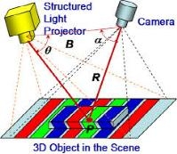
Image Source:osapublishing
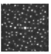
Behind the Kinect sensor is the structured light technology licensed by Israel's Primesense (now purchased by Apple). The principle is to avoid the complex algorithm design of binocular matching, instead of replacing one camera with an infrared projector that actively projects complex light spots, and the other parallel position camera has become an infrared camera, which can clearly see All spots projected onto the projector. Because the human eye can't see the infrared light spot, and the texture is very complicated, it is very beneficial to the binocular matching algorithm, and the depth information can be identified with a very simple algorithm.
Although Kinect's internal principles have not been explained by the authorities, in a Kinect Unleashed article in recent years, the author has hacked the public how this system works:
First, the infrared image is sampled 8 times in the baseline direction, which can guarantee 3bit sub-pixel accuracy after binocular matching. Then, the image is sobel filtered so that the matching accuracy of the image is improved. Then, the image and the pre-stored projection spot template image are subjected to SAD block matching. The algorithm has low computational complexity and is suitable for hardening and parallelism. Finally, after a simple image post-processing, down-sampling to the original resolution, the final depth map is obtained.
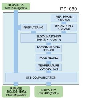
Source: Martinez, Manuel, and Rainer Stiefelhagen. "Kinect Unleashed: Getting Control over High Resolution Depth Maps." MVA. 2013.
We can see that with the explosion of the Kinect equipment in the consumer market in 2009 (one million units in the first 10 days of sale), the development of similar technology variants in mobile devices has gradually begun to boom. From 2013 till now, with the increase of computing power and advances in algorithms, active/passive binocular depth cameras with lower hardware costs have begun to emerge on mobile handsets.
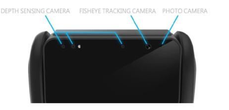
The binocular matching algorithm, which was considered difficult to run in real time in the past, showed excellent 3D imaging quality even without active light assist. The Segway robot uses an active/passive switchable binocular depth vision system. As shown below,
The left three sensors are left infrared camera, infrared pattern projection, right infrared camera. When working indoors, the infrared projection is turned on because of the lack of infrared light source, and the auxiliary binocular matching algorithm is used. When working outdoors, the infrared light source is sufficient and the infrared projection is turned off. The binocular matching algorithm can operate directly. Taken together, this system exhibits excellent depth sensing capabilities both indoors and outdoors.
Q: How does the robot implement navigation after visual processing?
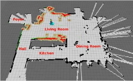
Image source: pirobot
Robot navigation itself is a more complex system. The technologies involved include the following list.
• Vision odometer VO
• Construction, use of VO and depth maps
• Relocate to identify the current location from a known map
• Closed-loop detection • eliminates the closed-loop error of VO
• Global navigation
• Visual obstacle avoidance
• Scene tagging, identifying objects in the room plus tags
When the robot is turned on, the visual odometer will start to work and record the 6DOF positioning information from the start position. During the movement of the robot, the mapping algorithm begins to construct the world seen by the robot, and the information of the rich feature points in the space and the two-dimensional map information are recorded in the robot map.
When the robot loses its own coordinates due to occlusion, power off, etc., the relocation algorithm needs to locate the current position estimate of the robot from the known map. In addition, when the robot moves back to the position once appeared in the map, the deviation of the visual odometer may cause the trajectory to not completely close. This requires the closed-loop algorithm to detect and correct this error.
With the global map, the robot can give some target point instructions and do global autonomous navigation. In reality, because the environment is constantly changing, the global map does not fully reflect the status of obstacles during navigation. Therefore, the visual obstacle avoidance algorithm above the global navigation needs to be adjusted in real time.
Finally, an automated navigation system also requires the robot to automatically recognize and understand the information, location, height, and size of different objects in space. The tag information is superimposed on the map, the robot can semantically understand its environment, and users can also give instructions from a higher level.
Q: What are the difficulties with visual VSLAM implementation on robots?
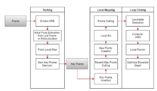
Visual VSLAM is an algorithmic system that integrates visual odometry, mapping, and repositioning. In recent years, it has developed rapidly. The feature-based visual SLAM algorithm starts from the classic PTAM algorithm. Currently, the algorithm represented by ORB-SLAM can already reach real-time running on the PC. Here is a block diagram of an ORBSLAM:
Visible from the name, it uses ORB as an image feature extraction tool, and uses the same feature point information in subsequent map creation and relocation. Relative to the traditional SIFT and SURF feature extraction algorithms, the efficiency is much higher.
The ORB-SLAM contains three parallel threads, namely trace, build and closed loop. The trace thread runs at the front end to ensure real-time running. The build and closed loop threads run at the back end. The speed does not need to be real-time. However, sharing the same map data with the trace thread can be corrected online to make the map data with higher precision and tracking accuracy. The figure below shows the main data structure of the ORB-SLAM map.
Point clouds and keyframes. A mapping relationship between 2D feature points and point clouds in space is established between the two, and the relationship between the key frames is also maintained. Through these data associations, the entire map is maintained using optimization methods.
The ORB-SLAM application on robots still has the following difficulties:
1. The amount of computation is too large, which usually takes up about 60% of CPU resources on a 4-core processor.
2. When the robot moves too fast, it will be lost and unrecoverable.
3. There is a problem of uncertainty in the size of monocular SLAM. This problem is especially noticeable when the robot is rotating fast, and soon there will be situations where the closed-loop error is too large to be corrected.
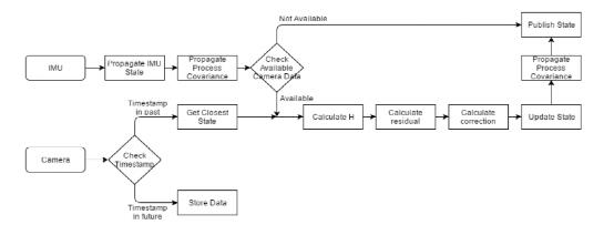
For scaling problems, there are two methods to solve: add a camera to form a binocular SLAM system, or add an IMU to form a loosely coupled/tightly coupled visual inertial navigation system. A loosely coupled visual inertial navigation system is briefly introduced here. VSLAM is generally treated as a black box, and its output is placed as an observation in an IMU-based EKF system. The output of the EKF's final fuse is the output of the system.
Considering that the camera data and the IMU data are usually not synchronized, the time stamp corresponding to the image data needs to be determined by the hardware time stamp and the IMU time stamp. In the EKF propagate step, the higher frame rate IMU data constantly updates the state of the EKF. When the camera data arrives, the EKF update step is triggered, the state variables, the covariance matrix are updated according to the EKF modeling equations, and all the state variables corresponding to the IMU data that is later than the camera data are updated.
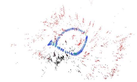
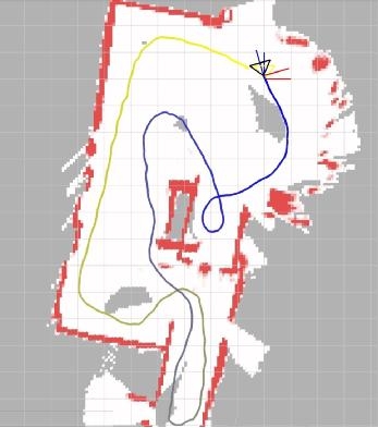
Segway Robot uses the industry-leading visual inertial navigation positioning system. The following is an effect diagram of running a circle in a corridor and returning to the original point. Specifically, it has the following advantages:
1. Guaranteed very small closed-loop error at large scale
2 real-time operation, the demand for CPU resources is small
3 allows rapid rotation and other situations, will not lose
Q: What is the principle of visual obstacle avoidance algorithm?
The problem solved by navigation is to guide the robot towards the target. When the robot has no map, the approach to the target is called visual obstacle avoidance. The problem solved by the obstacle avoidance algorithm is to hide the static obstacles and the dynamic obstacles according to the data of the vision sensor, but still maintain the movement in the direction of the goal and real-time autonomous navigation.
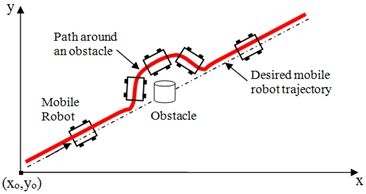
Image Source:sciepub
There are many obstacle avoidance algorithms, however, these methods all have strict assumptions, assuming that the obstacle is circular or that the robot is circular, assuming that the robot can move in any direction, or that it can only take a circular path. However, in practical applications, it is difficult for the robot to reach the conditions. For example, the VFF algorithm assumes that the robot is a point and can move in any direction. VFH+ assumes that the robot is circular and passes through a circular expansion obstacle. It only assumes that the robot moves in a circular path when considering kinematic problems. The DWA also assumes that the robot is circular, and only considers the forward arc motion when considering kinematics.
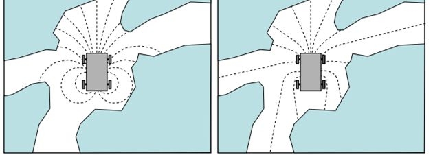
In contrast, we do not limit the shape of the robot. When considering kinematics, simulate a variety of motion models, not limited to arc motion, because it can find better behavior for the robot to avoid obstacles.
This figure shows that using different kinematic models leads to different obstacle avoidance results. The left image shows the simulated path using the arc model, and the right image shows the simulated path using another path model. In this narrow environment, this method can predict the obstacles in multiple directions in advance. Choosing the right model can help find a more suitable direction to avoid obstacles.
The difference between the currently used obstacle avoidance algorithm is that it abstracts the kinematic model into the surrounding map, and then any commonly used obstacle avoidance algorithm can be used, thus decoupling the kinematic model from the algorithm. And any demanding obstacle avoidance algorithms can be added. Segway Robot's obstacle avoidance system combines sensor depth, ultrasonic, IMU and other sensors. In a complex environment, you can easily avoid obstacles.
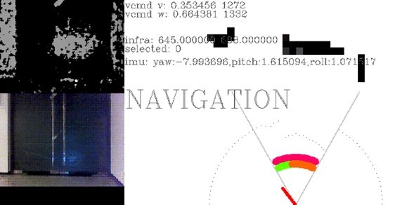
This picture is a screenshot of our obstacle avoidance system. You can see the depth map and the 2D obstacle avoidance map. The bottom red pointer represents the decision to avoid obstacles every moment.
Wonderful question and answerQ: Why use ir camera instead of traditional rgb camera? What are the advantages of ir camera?
A:ir The camera can see objects that cannot be seen by the human eye. For example, the depth camera needs to project infrared textures indoors to help identify the depth. The human eye can't see it, but the ir camera can see it.
Q: Is robot navigation mainly slam technology and no other navigation technology? What are the main popular slam technologies? What are the similarities and differences between visual navigation techniques for drones and drones?
A: The slam technology is a basic module in navigation. There are many types of slam technology, such as monocular, binocular, depth, imu+visual and other sensor-based algorithms. Binocular cameras can be well adapted to indoor and outdoor environments. His volume is actually very small, and the length of the camera used by the segway robot is about 10cm.
Q: Is there a navigation map for robot navigation now, similar to a car navigation map? What are the map data for robot navigation?
A: There is no such robot navigation map yet, but it is a research and development hotspot. Such as tesla and mobileye map battle. We will release the developer version of the robot in the second half of this year. You can apply at robot.segway.com.

Interactive Kiosk,Interactive Kiosk Software,Interactive Touch Screen Kiosk,Interactive Wayfinding Kiosk
Guangzhou Winson Information Technology Co., Ltd. , https://www.winsonintelligent.com