
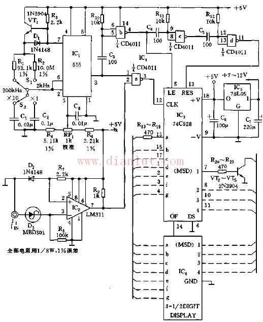
As shown in the figure, the multivibrator is composed of IC1, R1, R2, C1, C2, and VT1. R3, VT1, D1, etc. constitute a constant current charging circuit to keep the linearity of its charging. The shift switches S1, S2 enable the output strobe pulses of IC1 to provide gate pulses of 1000ms, 100ms, 10ms and 1ms.
IC2 and R7, D2, R6, etc. form an input adaptation circuit for receiving a square wave, sine wave or triangle wave of ±0.3~±0.9V. The four-input NAND gate IC4 is used to provide the inverting and delay. C5 and R10 function as differential circuits to provide differential narrow pulses for IC4-b and to reverse the output.
Magsafe Power bank,Baseus Power Bank,Best Power Bank 2021,power bank magsafe
Pogo Technology International Ltd , https://www.wisesir.net