
The I2C (Inter Integrated Circuit) bus is a low-cost but efficient network for interconnecting peripherals in small-scale embedded systems. The I2C bus is sometimes called IIC, which has been around for more than 20 years. The I2C interface works the same as the SPI interface, but the methods of use are somewhat different.
The I2C bus uses two wires to connect multiple devices in a multi-drop bus. This bus is bidirectional, low speed and synchronized to the common clock. A device can be directly connected to or removed from the I2C bus without affecting other devices. Some manufacturers, such as Microchip, Philips, Intel, and others, have built-in I2C interfaces. The I2C bus has a slower data transfer rate than the SPI bus, with a transfer speed of 100kbps in standard mode and 400kbps in fast mode. The two wires used to connect between devices using the I2C interface are SDA (serial data) and SCL (serial clock), which are open-drain and connected to the positive supply through a pull-up resistor, so they are not used. When throwing to keep high. Devices that communicate using the I2C bus drive the two lines to a low level, keeping them high when not in use. Each device connected to I2C has a unique address. This device can be a data sender (bus master), a receiver (bus slave), or both. I2C is a multi-master bus, which means that multiple devices can act as bus masters.
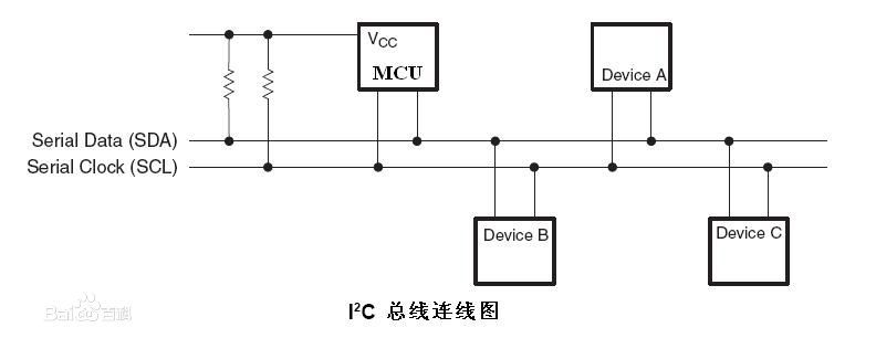
Figure 1. I2C bus connection diagram
Both SDA and SCL are bidirectional. The SPI bus has two separate lines for communication in both directions. Unlike the I2C bus, it uses the same line to complete the host transmit data and receive slave response. In addition, unlike the SPI bus, which has multiple operating modes, the I2C bus has only one operating mode. The timing relationship between the clock line SCL and the data line SDA is simple and straightforward: when idle, SDA and SCL are high, only Data transfer on the I2C bus begins when SDA goes low and then SCL goes low. When both SDA and SCL go low, it tells the transfer of all receive device packets on the bus. After SCL goes low, SDA sends the first valid data bit. This is called the start condition. . For each bit transferred, it must be asserted on SDA when SCL is low. This bit samples the data bits on SDA on the rising edge of SCL and must remain active until SCL changes again. Low, then SDA transfers the next bit before SCL goes high again. Finally, SCL goes high, then SDA also goes high and the data transfer ends. This is called the end condition.
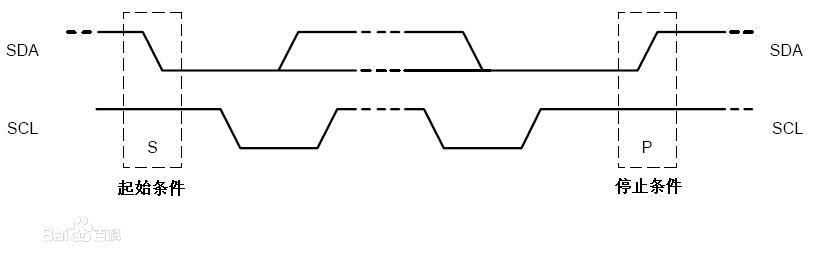
Figure 2. Start and End Conditions for I2C Bus Transfer
No matter how large the data packet can be transmitted over the I2C bus. Like the SPI bus, I2C is also high-order first. If the data receiver can no longer receive more data, it can interrupt the transmission by holding SCL low, which forces the data sender to wait until SCL is re-released. Each byte sent by the sender must be acknowledged by the receiver. Once the 8th bit of each byte is transmitted, the sender releases the data line SDA, and the host generates an additional clock pulse on SCL. The trigger receiver indicates that the received byte is acknowledged by asserting SDA low. If the receiver fails to set SDA low, the sender will interrupt the transfer and take appropriate error handling.
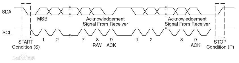
Figure 3. I2C packet with receiver acknowledgment
Since I2C is a multi-master bus, there are times when multiple hosts attempt to start data transfer at the same time. The SPI bus uses a separate chip select to make the receive slave active. Each SPI slave has a separate chip select that is driven by the host. I2C does not have such a selection mechanism, but each device on the bus has a unique address, which is sent first when the packet is transmitted, followed by the data. An address byte consists of 7 address bits and 1 indicator bit. If the indicator bit is 0, meaning that the transfer is a write operation, the selected slave will receive the data and take it as input; if the indicator bit is 1, the slave is required to send the data back to the host.
The I2C bus also supports an extended 10-bit addressing mode with up to 1024 connected peripherals. Devices using 7-bit addressing mode and 10-bit addressing mode can be mixed in the same system. For 10-bit addressing, use 2 bytes to save the address. If the first address byte starts with 0b11110xx_, a 10-bit address is generated, the first and second bits of the first byte (the 0th bit is the read/write indication bit) and the 8th bit of the 2nd byte. Together they form a 10-digit address. The 7-bit device will ignore this process.
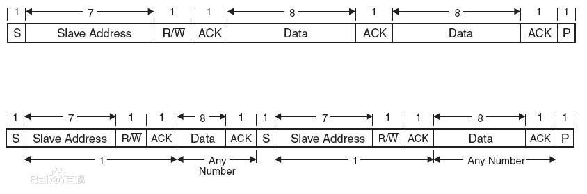
Figure 4. I2C normal and 7-bit address format with repeated start conditions
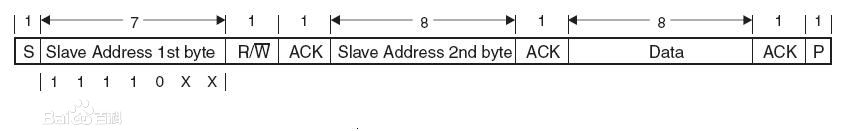
Figure 5. I2C bus 10-bit address format
car key cover,key holder for keychain,car key fob cover,key fob protector,honda accord accessories
Dongguan Metalwork Technology Co., LTD. , https://www.dgdiecastpro.com