
TD-LTE picocell base station test
1 Introduction
Picocell, similar to Home Node B, is a small, low-cost cellular access point that is mainly used to improve network coverage in personal residences and small business buildings. Usually, it is directly connected to the operator's core network through a method similar to DSL or cable broadband; it operates basically the same as the base station, except that its power level is lower than that of the general base station, and its RF performance can also be slightly reduce.
At present, China will fully move towards the 3G era. The full advent of the 3G era has provided a wealth of imagination for the market for its subsequent LTE technology. As the time division mode TD-LTE of LTE technology, because it is fully compatible with TD-SCDMA and can provide a very smooth technology transition for TD-SCDMA technology, it has aroused widespread concern in China's communications manufacturers. As a combination of ultra-microcells and TD-LTE that improve the last level of coverage, it will undoubtedly greatly increase the coverage of TD-LTE in personal residences and small business buildings, thereby having more physical resources that can be allocated to customers and greatly improving users Customer experience.
2 TD-LTE frame structure
In the long-term evolution (LTE) of UMTS, there are two modes: frequency division (FDD) and time division (TDD). TD-LTE is its time division mode, also known as LTE-TDD; it is completely consistent with FDD in high-level protocols, and fully considers and inherits the design idea of ​​TD-SCDMA in frame structure, except for FDD at special subframes Apart from the slightly different modes, other subframes also maintain good compatibility with the FDD mode.
In the two frame structures in LTE, FDD uses Type 1, and TDD uses Type 2. The Type 2 frame structure used by TD-LTE is very similar to TD-SCDMA. It divides a 10ms radio frame into two 5ms half-frames; each half-frame consists of 5 1ms subframes, including a special Subframe and 4 normal subframes. For a special subframe, it is composed of three special time slots: DwPTS, GP, and UpPTS; DwPTS is a downlink pilot time slot, UpPTS is an uplink pilot time slot, and GP is used for the guard interval between downlink and uplink. Ordinary subframes are used to transmit data information as in FDD mode.
Unlike LTE-FDD (relying on frequency to distinguish between uplink and downlink), LTE-TDD is on the same frequency, depending on time, that is, different time slots to distinguish between uplink and downlink, so it can be easily satisfied by adjusting the ratio of uplink and downlink time slots Demand for many asymmetric services in real networks. In the specification, 7 different upstream and downstream ratios are defined, from 9: 1 with more support for downlink to 2: 3 with more support for uplink. Users can choose according to their needs, so as to achieve download or upload services. Good support.
3 TD-LTE picocell test
LTE technology (TDD and FDD) uses a completely different air interface from CDMA (mainly used in third-generation mobile communications) code division multiple access technology, which uses OFDMA (Orthogonal Frequency Division Multiplexing Multiple Access) in the downlink (Incoming) technology, using SC-FDMA (Single Carrier Frequency Division Multiple Access) technology with optimized peak-to-average ratio on the upstream, which poses a huge challenge to the testing of LTE equipment. Figure 1 is a block diagram of the RF test of a TD-LTE picocell base station according to the specification TS36.141 using the vector signal source SMU200A and vector signal analyzer FSQ of Rohde & Schwarz.
Figure 1 Schematic diagram of testing picocells using R & S's SMU and FSQ
At present, because LTE technology is still developing, its corresponding technical specifications have not been completely frozen. In the TS 36.141 V 8.2.0 version, the test of the base station transmitter has defined such as power, transmitted signal quality (including frequency error, vector amplitude error EVM, time comparison relationship between different antennas, downlink reference power, etc.), spectrum (Including occupied bandwidth OBW, adjacent channel leakage ratio ACLR and spurs, etc.) and transmitter intermodulation. Using R & S's FSQ, you can test all of the above indicators. In addition, you can test the EVM, power time mask, frequency flatness, constellation diagram, CCDF, and bitstream on each carrier and each subframe; these test functions further expand R & D personnel The breadth and depth of the test accelerated the progress of research and development.
For the LTE transmitter test, the biggest difference from the traditional mode test is that it needs to support MIMO technology. The above test items related to it have different time comparison relationships between different antenna test items; the principle is to test two or more antennas Time, under normal working conditions, the time error between their respective transmitted signals. Using R & S's vector signal analyzer FSQ (or FSV), this test can be achieved with one meter (see Table 1 for test results); not only that, but also the signal quality of each antenna. During the test, you only need to link the two antennas of the base station to the radio frequency port of the FSQ through the combiner, and select the function keys inside the FSQ to get the corresponding test results. 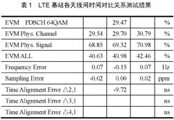
TD-LTE receiver and performance test, the vector signal source generates the corresponding uplink signal (SC-FDMA), and the reception of the base station is verified through the single-ended receiver test. The so-called single-ended is the signal sequence sent by the known signal source of the base station. After receiving and demodulating, it compares itself and calculates the test result BER / BLER. The following test items are defined in the corresponding test specifications:
(1) Reference sensitivity.
(2) Dynamic range.
(3) In-band selectivity.
(4) Adjacent channel selectivity and narrow-band blocking.
(5) Block.
(6) Receiver spurs.
(7) Receive intermodulation, etc.
(8) Performance test under HARQ retransmission and multipath fading.
(9) Uplink timing adjustment performance test under HARQ retransmission.
Receiver spurs can be tested with a spectrum analyzer. The other tests above can be implemented using the dual-channel vector signal source SMU200A. The SMU200A can be configured as dual channels. One channel generates the uplink TDD LTE signal, and the other channel generates the interference signal required by the specification. These interfering signals can be single tones or vector modulation signals of different standards, which can add fading and AWGN noise to each channel independently. In the performance test, the SMU200A can retransmit the uplink signal in real time according to the feedback signal of the base station, which is impossible for the arbitrary waveform generator.
In addition, MIMO (Multiple Input Multiple Output) technology is an indispensable component of LTE. The high-speed implementation of LTE is indispensable for the support of MIMO technology, so it is necessary to use the corresponding MIMO signal to test the performance of the base station receiver. At this time, you can also use the 4 fading modules built in the dual-channel SMU200A to test 2 × 2 MIMO, see Figure 2 for details.
Figure 2 SMU generates 2 × 2 MIMO test signals
4 Conclusion
At present, although the technical specifications related to LTE have been mostly frozen, there are still some indicators that are constantly changing and developing. For testers, they need to use equipment that can closely follow the specifications to test their LTE products and maintain the products. Leading. Rohde & Schwarz has a very close relationship with 3GPP and is one of its members. It has always followed the development of LTE and launched corresponding test functions, fully supporting the evolution of TD-SCDMA to TD-TLE in China.
Common Mode Coil For Automotive Product,Magntic Inductor Coil,Emi Common Mode Choke,Common Mode Coil Inductor
IHUA INDUSTRIES CO.,LTD. , https://www.ihua-magnetics.com