
PESD1CAN electrostatic protection SOT23-3 24V two-way
5V, 35pF, bidirectional ESD protection diode
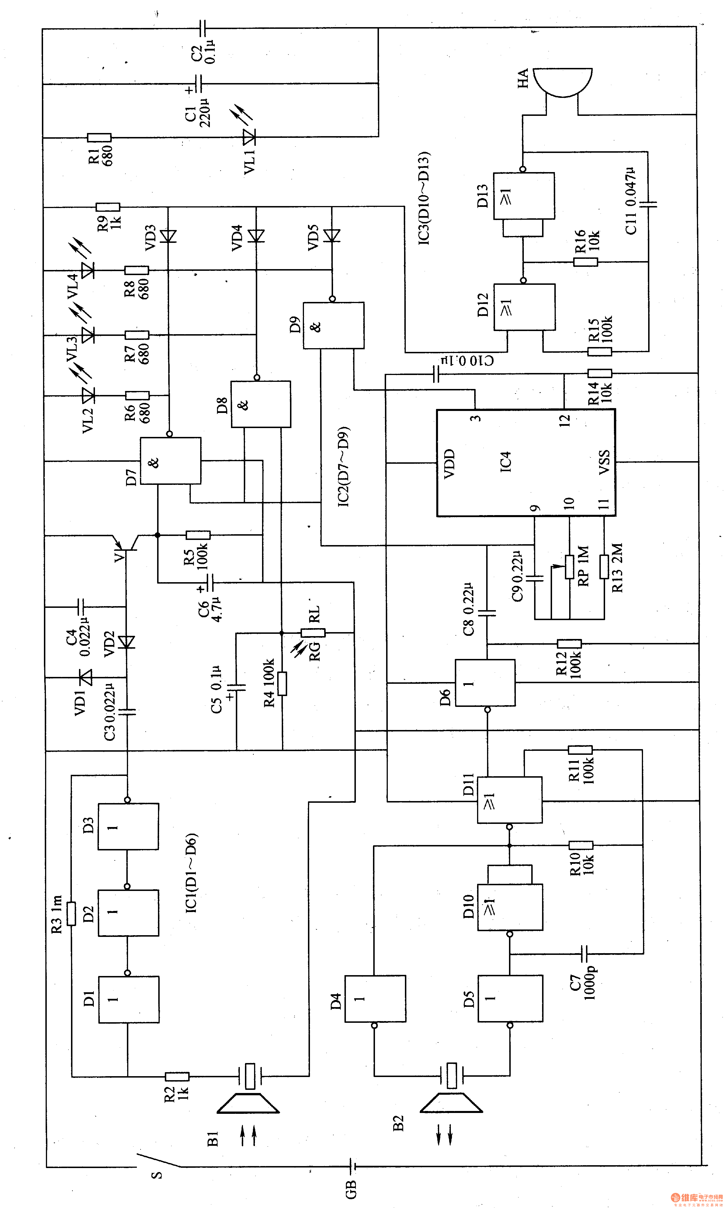
The ultrasonic transmitting circuit consists of an ultrasonic transmitter B2, a D4-D6 inside the non-gate integrated circuit ICl (Dl-D6), a NAND gate integrated circuit IC3 (DlO-D13), a NAND gate D10, a D11, and a resistor R10-Rl2. It is composed of capacitors C7 and C8.
The ultrasonic receiving control circuit is composed of an ultrasonic receiver B1, resistors R2, R3, R5, lCl internal non-gate D1-D3, NAND gate integrated circuit IC2 (D7-D9) internal D7, capacitor C3-C6, diode VDl, VD2, transistor V composition.
The photometric routing photo resistor RG, the resistor R4, the capacitor C and the NAND gate D8 inside the IC2 are composed.
The timing control circuit is composed of a timer integrated circuit IC4, resistors R13, R14, capacitors C9, ClO, a potentiometer RP, and a NAND gate D9 inside the IC2.
The LED indicating circuit is composed of light emitting diodes VLl-VL4, resistors R1, R6-R9 and diodes VD3-VD5.
The power circuit is composed of a battery GB, a power switch S, and capacitors C1 and C2.
The audible warning circuit is composed of NAND gates DI2, D13, resistors R15, R16, capacitor C11 and buzzer HA inside IC3.
Turn on the power switch S, and the whole circuit of the whole machine is energized. The 3kHz square wave oscillation signal outputted by the 9th pin of lC4 is added to one input terminal of the NAND gate D7-D9, and the other path is added to the input terminal of the non-gate D6 via C8. The square wave oscillation signal is shaped by D6. The 4OkHz oscillator (composed of NAND gates D10, D11 and C7, R10, and R11) modulates, and the modulated oscillating signal is driven by the non-gates D4 and D5 to emit ultrasonic waves.
When the distance between the user's face and the writing surface is greater than 35cm, B1 can not receive the ultrasonic signal emitted by B2, VD2 and V are in the off state, NAND gate D7 outputs the high level, VL2 does not emit light, and the sound warning circuit Not working, HA does not speak. When the distance between the face of the user and the writing surface is less than 35 cm, the ultrasonic signal emitted by B2 is reflected back by the human face, and B1 receives the reflected ultrasonic signal and converts it into a corresponding electrical signal, the electrical signal After the non-gate Dl-D3 amplification shaping and C3, VDl, VD2, C4 double-pressure detection, a negative DC voltage is generated, V is turned on, and a NAND gate D7 outputs a rectangular pulse signal of 3 kHz, and VL2 is flashing; meanwhile, VD3 intermittent conduction Through, the audio oscillator composed of the NOR gates D12, D13 and Rl5, R16, C11 oscillates under the control of the 3 kHz pulse signal, and drives the HA to emit intermittent buzzing sounds to remind the user to pay attention to the reading and writing distance.
When ambient light is suitable for reading and writing, the resistance of RG is small, NAND gate D8 outputs high level, VL3 does not emit light, VD4 is in the off state, the audio oscillator does not work, HA does not sound. When the ambient light is weak and the reading and writing requirements are not met, the resistance of RG becomes larger, so that the NAND gate D8 outputs a rectangular pulse signal of 3 kHz, VL2 flashes, and VD4 intermittently turns on, so that the audio oscillator oscillates, HA A warning sound is issued to remind the user that the ambient light is weak and the desk lamp should be turned on.
When the timing time has not expired, IC4's 3 pin outputs a low level, NAND gate D9 outputs a high level, VL4 does not emit light, VD5 is in an off state, the audio oscillator does not work, and HA does not sound. When the timing time is over, the 3 pin of lC4 becomes high level, and the NAND gate D9 outputs a rectangular pulse signal of 3 kHz, so that VL4 flashes, the audio oscillator oscillates, and the HA sounds a warning to remind the user to take a break.
Adjusting the resistance of RP can change the frequency of I called the internal oscillator, so that the signal frequency of the 9-pin output is 3 kHz.
Component selection
Rl-R16 uses 1/4W metal film resistors.
The RP uses a small organic solid potentiometer or a variable resistor.
RG uses a photoresistor with a light resistance of less than 2kΩ and a dark resistance of more than 2MΩ.
Both Cl and C6 use aluminum electrolytic capacitors with a withstand voltage of 16V; C2-C5 and C8-Cll all use monolithic capacitors; C7 uses high-frequency ceramic capacitors.
VDl-VD5 selects 1N4148 type silicon switch diode for use.
V selects S9012 or C8550 type silicon PNP transistor.
VLl-VM uses φ3mm high-brightness LEDs.
ICl selects CD4069 type six non-gate integrated circuit; IC2 selects CD4011 type four NAND gate integrated circuit; IC3 selects CD400l or CC4001 type four or non-gate integrated circuit; IC4 selects CD4060 type timing/divider integrated circuit.
HA uses a piezoelectric buzzer.
Bl selects UCM-40R ultrasonic receiver; B2 selects UCM-40T ultrasonic transmitter.
S uses a small single-pole toggle switch.
GB uses 6V laminated battery or 4 series 5th battery in series.
Minsound offers a great range of Driver Units,providing accurate reproduction.high intelligibility and dependable performance in commercial sound,signaling and public address loudspeaker systems.
All models are suited for Minsound reflex horns,equipped with the industry standard 1-3/8"-male tread pattern.
This series driver units are made of Neodymium magnet for good performance.
Neodymium Driver Units,Neodymium Driver,Neodymium Drivers,neodymium speaker magnets,Neodymium magnets
Taixing Minsheng Electronic Co.,Ltd. , https://www.ms-speakers.com