
At present, countries around the world are studying 42VDC automotive power systems. The European Community plans to adopt 42VDC power systems from 2008. How to be compatible with 12VDC electronic devices under the 48VDC power system has become a topic. The conversion of 42VDC/12VDC through a linear regulated power supply will result in a large power loss, and the disadvantages are obvious.
This paper presents a switching power supply design scheme for an onboard power supply system with overload and short circuit protection. The solution adopts a single-ended flyback structure to realize 42VDC/12VDC conversion, stable output voltage, small ripple, uninterrupted, reliable performance and low power loss.
UC3842 protection circuit design
1 Typical application of UC3842The UC3842 is a high performance single-ended output current-controlled pulse width modulation (PWM) chip. The typical application circuit is shown in Figure 1.
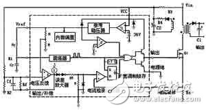
Figure 1 UC3842 typical application circuit
2 Analysis of overload protection principleWhen an output short circuit occurs, the output voltage drops, and the output winding drops for the feedback winding that supplies the UC3842. When the input voltage is lower than 10V, the UC3842 stops working and the switch is turned off. After the short circuit disappears, the power is restarted and the operation resumes automatically.
However, due to the high peak voltage when the high frequency is turned off, even if the duty ratio is small, the input voltage of the 7-pin in the circuit may not be low enough, and the overload protection circuit may not always be able to The overload situation caused by effective response will have a bad impact on the performance of the whole system, and there are certain security risks.
3 Analysis of the principle of overcurrent protectionWhen the voltage value on the pin 3 of the current sampling terminal exceeds the voltage at the negative terminal of the current detecting comparator, the pulse width modulation latch can be input to the reset signal, and the switching transistor is then turned off. Thus, the peak detection circuit limits the maximum current output and provides a certain protection.
However, as the switching frequency increases, it may happen that the switching power supply is in continuous mode, that is, the primary inductor current of each switching cycle starts to increase from a certain amplitude, which causes subharmonic oscillation. This instability is independent of the closed-loop characteristics of the regulator, which is caused by the simultaneous operation of fixed frequency and peak current sampling. Figure 2 illustrates such a phenomenon.
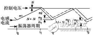
Figure 2 Current waveform before compensation
As shown in Figure 2, at time t0, the switching transistor is turned on, at which point the primary coil current rises with a slope m1 as a function of input voltage and inductance. At time t1, the current sample input reaches the threshold of the current sense comparator, which causes the switch to turn off and the current to decay at slope m2 until the next switch cycle. If a disturbance is applied to the threshold voltage of the current-sense comparator, a small ΔI (shown by the dotted line in Figure 2) is generated, and instability occurs. During a fixed oscillation period, the current decay time decreases, and the minimum current rises by ΔI + m 2 / m 1 at the turn-on timing (t 2) of the switch. The minimum current is reduced to (ΔI + m 2 / m 1) · (m 2 / m 1) in the next cycle (t 3).
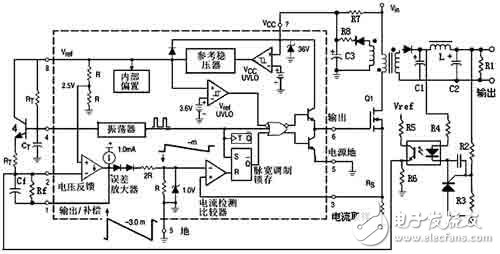
Figure 3 block diagram of the switching power supply
During each subsequent switching cycle, the disturbance is multiplied by (m 2/m 1), the primary coil current is alternately increased and decreased over several switching cycles, and the current may be reduced to zero after several switching cycles. This process begins again. If m 2/m 1 is greater than 1, the system will be unstable.
4 improvement of protection circuitAs shown in Figure 3, this design makes the following improvements for the overcurrent and overload protection circuits of the UC3842 typical application circuit.
In the rectifier winding circuit of the feedback winding, a resistor is formed, and the capacitor C2 forms an RC filter network, which filters the spike voltage at the moment when the switch is turned on. Thus, due to the reduction of the spike voltage, when the short circuit occurs, the voltage output from the feedback winding will be effectively reduced, and the UC3842 will stop working until the short circuit is released.
Slope compensation for the overcurrent protection circuit. The compensation slope is generated from the RT and CT oscillators and applied to the voltage feedback terminal to improve the slope compensation of the error amplifier output. As shown in Figure 3, the output of the error amplifier is a ramp with a slope of m3. After passing through two diodes, it is divided by a resistor and then input to the negative terminal of the current sense comparator as the control voltage of the overcurrent protection circuit. This allows the configuration of the current sense comparator and the pulse width modulation latch to ensure that only one single pulse appears at the output during any one oscillator period. When there is an abnormal operation such as overload or loss of output voltage sampling, the internal comparison threshold will be limited to 1V without circuit offset.
Figure 4 shows that by adding an artificial ramp to the control voltage that is synchronized with the pulse width modulated clock, it is possible to effectively suppress instability due to ΔI disturbances in subsequent switching cycles. The slope (m 3 ) of the compensation ramp must be equal to or greater than m 2/2 to have stability. With the compensation of the m 3 slope, the primary coil current is suppressed by the control voltage, following the magnitude of the control voltage.
Experimental resultTable 1 shows the fluctuation of the output voltage when the input voltage fluctuates between 30 and 50 V. Table 2 shows the fluctuation of the output voltage when the load current changes from 10 to 500 mA. The voltage adjustment rate S v can be obtained from the data of Table 1.
India Modular Wall Switch And Socket
India Modular Wall Switch And Socket,India Modular Wall Switch,India Modular Wall Socket,Best India Modular Wall Switch
ZHEJIANG HUAYAN ELECTRIC CO.,LTD , https://www.huayanelectric.com