
DLP projection technology is a technology that uses Digital Micromirror Device (DMD) developed by Texas Instruments as the main key processing element to realize the digital optical processing process. The DLP display has high color definition, vivid, delicate, and vivid, and it is highly reliable for all-digital display, and can be used in various products (such as large-screen digital TVs, company/home/professional conference projectors and digital cameras (DLP). Cinema)) provides the best image effect. At present, most of the domestic or commercial DLP projectors adopt a monolithic structure, which makes them easy to carry and carry, and thus have been more and more widely used. On the basis of the current application development, higher requirements are also put on the simplicity and portability of the structure. The traditional DLP projector receives the external signal through the DVI interface and transmits the signal to the DLP controller to control the display of the DLP. The space occupied is large and the mode of the received signal is more limited, and it is difficult to integrate into the existing equipment. If the digital signals in the existing instruments can be directly sent to the DLP without multiple data conversions, the size and cost can be reduced, and the DLP can be easily integrated into the instrumentation instrument.
DLP projectors use tricolor LEDs as the light source, which is also crucial for LED selection. In recent years, RGB tri-color LLEDs have surpassed other light emitting devices in terms of heat dissipation, reliability, color saturation, and energy efficiency. The use is also more and more common. Many LED device manufacturers currently use independent combinations of red, green, and blue LEDs to provide the desired color. There are disadvantages in using discrete LED packages for applications, such as space waste caused by conforming to the package structure, and Separating distant light sources requires extra effort to achieve effective color mixing, and therefore requires an integrally packaged LED chip to replace the traditional stand-alone light source, ie a product that integrates red, green, and blue LED chips in a single package, where each An LED chip can be controlled independently, providing a variety of different color output.
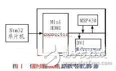
In this paper, the DLP1700 is taken as an example to improve the traditional DLP projection system from the two aspects of signal input control and display light source. The display light source adopts high-power RGB three-color LED to replace the traditional multi-color single-color LED, signal input control On the other hand, the traditional DVI connector and MSP430 are cancelled. The control signal and the image signal generated by the Stm32 microcontroller with I2C function directly control the DLP1700 controller DLPC100, thereby controlling the display of the DLP1700. The design can make the hardware circuit structure of the DLP display device more streamlined, the circuit control is easier to implement, and can be easily integrated into various instruments.
1 signal input controlThe signal input end of the traditional digital micromirror display technology is provided by the DVI interface to provide image signals and line-field synchronization signals. The DLPC100 is basically controlled by the MSP430 microcontroller, and the control signal is transmitted through the I2C bus. The whole process involves the chip. More, the circuit is more complicated. In this paper, we use the STM32 series MCU based on Cortex_M3 core to improve the signal input part, and send the image signal and line field synchronization signal sent by Stm32 to DLPC100 to control the display of DLP1700 and LED drive. . Because the STM32 itself carries an I2C bus interface, it can replace the traditional MSP430 and I2C bus to perform a series of internal control on the DLPC100. Specific circuit connection block diagram shown in Figure 1.
The use of an integrally packaged RGB tri-color LED instead of a conventional, self-contained, multi-LED package allows the light source to be more compact and significantly reduces the distance between each individual light source compared to a discrete packaged device. To achieve good color mixing, the maximum distance between LED light sources should not exceed 5mm. The three-in-one approach can reduce this distance to only 1.5mm. After the LED pitch is reduced, the required area for effective color mixing can also be reduced at the same time. After research, it has been found that such an integrally packaged LED also has good efficiency in heat dissipation.
The design of the article uses the Moonstone series of 3W RGB tri-color LEDs from Anwar High-Tech Co., Ltd. The light source has a higher light intensity and a smaller volume. RGB tri-color LED light source performance parameters such as Table 1, single-chip RGB tri-color LED light source can replace the traditional halogen tungsten light and multi-monochromatic LED light source, to achieve the same effect of light space used only a fraction of the ordinary white LED , is a dozen of the traditional halogen lamp.

The optical design software is used to design the lighting system. The light source is modeled according to the parameters of the light source performance. The model of the RGB tricolor LED light source is shown in FIG. 2. The size of the three monochromatic LED light emitting chips in the figure is 0.8×0.8 mm 2 , and the monochromatic light sources are respectively a blue light emitting chip, a green light emitting chip, and a red light emitting chip. The distribution is shown in FIG. 2 . The light source exit angle is 120°, and the exit light is set according to the parameters provided in Table 1. Using this light source to design a lighting system such as a projector, a rear projection television, and a large screen display can simplify the structure, reduce the volume, and facilitate the operation.
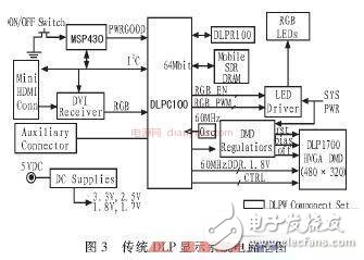
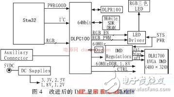
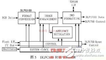
3 circuit principle and overall circuit diagramTraditional DLP1700 display system circuit diagram shown in Figure 3, the signal input to the diagram using DVI interface, MSP430 microcontroller, I2C bus line control is more complex; right from the DLPC100 output RGB EN and RGB PWM signal control LED driver and then control more than one Monochrome LED. The improved system circuit is shown in Fig. 4. The DLPC100 is controlled by the STM32 microcontroller and the data signal is input to the DLPC100, which in turn drives the LED driver. When the DLPC100 performs the data format conversion, signal enhancement, and DMD on the input signal data as shown in FIG. After the format conversion and other processing, the signal is transmitted to the DMD chip DLP1700. The 480×320 micromirrors on the DMD chip are deflected at a certain angle under the control of the input signal. The LED driver drives the tricolor LED to provide the light source for the DLP display, which is perfect on the screen. The image shows.
Above through the DLP1700 display circuit, optical system improved design, get a more simple and intuitive system, using STM32 series microcontroller to replace the complex input module design, it receives and processes digital signals and generates image signals, the input structure is simple, easy Programming control; replacing the traditional multi-color LEDs with a new type of packaged high-power RGB tri-color LED. Compared with the traditional discrete LED package, the three-in-one package solution can be used either in color mixing or space requirements. Having better performance, and having good heat dissipation and reliability, can bring more flexibility to engineering application development. The improved DMD display device is portable, simple in structure, small in size, energy-saving and environmentally friendly, and can be easily integrated into various devices, so that DLP instruments and equipment can better exert its advantages, namely, light weight, high reliability, easy operation and control, etc. To provide solid and powerful conditions for its larger-scale applications.
Camera Filter,Camera Polarizer Lens,Camera Raw Filter,Lens Filter
Shaoxing Shangyu Kenuo Photographic Equipment Factory , https://www.kernelphoto.com