
This paper divides the intelligent vehicle motion planning algorithm into graph search, sampling method, interpolation method and numerical optimization method from the different strategies. It comprehensively describes the evolution and advantages and disadvantages of the four algorithms. In the form of a timeline, the author also investigates the motion planning algorithms used and implemented by research units in the world of intelligent transportation systems. With regard to the future development of motion planning algorithms, the article considers that there are two major trends: the perception of uncertainty and movement; and the integration of the driver's large closed loop. This article is comprehensive and comprehensive. It elaborates on all mainstream planning algorithms and mainstream products that use these algorithms. It is worth mentioning. It is worth recommending to everyone.

Abstract: Using information such as infrastructure and other vehicles (V2I and car networking technology), vehicles can acquire environmental information in real-time through onboard sensors and communication networks. With these environmental information, different motion planning and control technologies can facilitate the realization of automatic driving in a complex environment. The focus of current motion planning research is on improving safety, comfort, and economy. However, obstacle avoidance in dynamic environments, synergy between automated and semi-autonomous vehicles, etc. are still challenging in the real world and require further research. This article is a review of the motion planning techniques in the autopilot literature. It also describes the methods of motion planning and the contributions made by the various research teams. The article also looks into the directions and applications for future research.
[motion planning]
Before the 1990s, due to the reduction in investment, the development of smart vehicles was very limited. Thanks to the development of vehicle automation information technology, the concept of intelligent transportation system has been formed. The investment of many research centers around the world (such as the Path team in California, the University of Parma, etc.) has injected a steady flow of power into the smart vehicle system. The history of the first self-driving concept car dates back to the late 1980s and early 1990s. At the time, in order to improve the serviceability of the highway system, Shladover et al. proposed a longitudinal control system for the vehicle (including following control of the vehicle, workshop communication, and comparison with other technologies) and a lateral control system (taking into consideration the lateral dynamics and magnetic force. Sensors act as path guides and do not involve path planning). And Behringer et al. proposed the integrated autopilot concept in the VaMoR-L vehicle - through visual and path generation, the vehicle can be driven autonomously (from its Prometheus project).
Subsequently, automated driving derived many control structures. As shown in Figure 1, perception, decision making and control are the main three blocks. This article focuses on motion planning techniques in decision making.
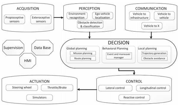
Figure 1 Automatic Drive Control Architecture
In recent decades, motion planning began as a research branch of mobile robots. Researchers also divide the motion planning into a global plan and a local plan. A large number of path planning technologies have migrated from mobile robots to autonomous vehicles and have been improved based on the requirements of road networks and driving rules faced. These planning techniques can be roughly divided into four categories according to the implementation method: graph search, sampling method, interpolation method, and numerical optimization.
Figure search
For autopilot, the basic idea is to traverse a state space from point A to point B. This state space is often represented by an occupied grid or lattice. The methods implemented in automatic driving include:
Dijkstra algorithm
This is a graph search method that finds the single source shortest path in the chart. The search space is approximated by a discrete cell, lattice [22,23]. Specific description and implementation of visible literature [24,25]. In terms of autopilot, the algorithm [26] implements the simulation of the algorithm in a multi-car scene. This algorithm is implemented on the Little Ben Autopilot [27] and the Victor Tango team [28]. The literature [29] realized the application of this algorithm in urban conditions.
A* algorithm
The core is how the node weights are determined. It is suitable for spatial search of vehicles with prior knowledge, but it also consumes storage and computing speed [30]. Some applications in the field of mobile robotics are adopted by autopilot and are improved as a basis. For example, dynamicA* (D*) [31], Field D* [32], Theta* [33], Anytimerepairing A* (ARA*) and Anytime D* (AD*) [34] and so on. Ziegler et al. implemented the A* algorithm in the unstructured space and parking spaces characterized by the Voronoi map [35]. Documents [36] and [37] are hybrid A* and A* applications for the Junior and Annie Way autopilot vehicles, respectively. The BOSS self-driving car uses the AD* algorithm [16].
State lattice algorithm
Using a state grid to form a discrete planning space. These grids are called state lattices and are based on this search planning [46]. Path search is based on a local series of state lattice queries or queries containing all possible features that allow the vehicle to move from one initial state to another. The cost function determines the best path for the state lattice map. A*[47] and D*[48] are implemented in this method. Howard and Kelly applied state lattices to the motion planning of wheeled mobile robots on rough terrain [49]. Simulations show that the method has global and local results. Literature [39] and literature [50] used the state lattice of the time dimension and velocity dimension.
Sampling method
This type of method is designed to solve time constraints (in high-dimensional space planning). This process involves the random sampling of feature space or state space and finding the connection of sampling points within this space [21]. The disadvantage is the suboptimality of the results. The most widely used among unmanned vehicles is the rapid random extension tree (RRT) [94].
The RRT is suitable for online path planning. By performing a random search in the navigation area, a quick search can be implemented in a semi-structured space [94]. It can also consider non-integrity constraints. Documents [21] and [95] describe this method. In terms of autonomous driving, the MIT team implemented the algorithm [61], but the result was not optimal and the path curvature was not continuous. Karaman et al. proposed an improved method of RRT*[96], which can obtain the optimal path, but there are other similar drawbacks. It is also described in [64].
Interpolation
For a given set of waypoints, Computer Aided Geometric Technology (CAGD) has a wide range of applications in path smoothing [73]. It can plan trajectories considering constraints such as performance, comfort, vehicle dynamics, and other parameters.
Interpolation is the process of constructing and inserting a series of new data points given a series of points in advance. This shows that the algorithm needs to predetermine a series of nodes and then generate a series of navigation trajectories that help the trajectory to be continuous and satisfy vehicle constraints and dynamic environment [97]. When facing an obstacle, it can create a new path (local path) for obstacle avoidance and return to the previously planned path (global path).
Straight line and arc method
Known road network can be segmented, insert a straight line or arc node at a known path point, so that the entire path is replaced by a straight line segment and an arc. This is a simple mathematical approach in the path planning of wheeled vehicles [41,98].
Convolution curve method
This type of curve is defined in the Fresnel coordinates (Fresnel integral) [73]. Since the curvature of the method corresponds to the arc length change, the clothoid curve can define the linear change of the trajectory according to the curvature; it can realize the smooth transition of the straight line segment and the curve segment on the curvature [42]. The convolutional curve is also used in the motion planning of high-speed, rail traffic, and car-like robots and can be implemented [99]. The VIAC project tested the implementation of the clothoid. In [69], the current curvature is obtained from the position of the steering wheel, and other parameters are considered based on dynamic constraints (such as tail swing) or physical constraints (such as steering wheel angle).
Polynomial curve method
This type of curve is usually used to meet the required constraints of the insertion point, and is more suitable for position fitting, rotation angle and curvature constraints. The starting and ending expectations and constraints determine the coefficient of the curve. In order to calculate the coefficients of the polynomial curve, reference can be made to [76, 77, 79].
The Lab for Vehicle-Infrastructure-Driver Interactions (LIVIC) implemented this algorithm in a lane change scenario [77]. The fourth-order polynomial curve is used to satisfy the longitudinal constraint, and the fifth-order polynomial curve is used to satisfy the lateral constraint. The literature [75] uses a cubic polynomial curve to generate the safety trajectory required for overtaking. The literature [43] implements cubic polynomial curves and quadratic polynomial curve programming in the state lattice.
Bezier curve
The shape of this parametric curve is determined by the control point. The core of the Bezier curve is the Bernstein polynomial. Since the curve is determined by the control point, the advantage of this method is that the amount of calculation is small. With the correct placement of the control points, the curve constraints of the start and end points can be satisfied [81, 100].
The literature [100] shows a good modular and extensible example of the Bezier curve. The literature [102] has designed a curved track connecting the curvature and the continuous Bessel curve. These curves are often used to approximate the clothoid [103,104], or to replace the strict Bessel curve in fast planning [85,86]. The literature [81,83,44] implemented three- and four-order Bezier curves on autopilot and evaluated the best operating curves for different scenarios (steering, circuitous, lane changing, obstacle avoidance, etc.).
Spline curve
It is a piecewise polynomial parametric curve. The segmented curve can be a polynomial curve [28, 76], a B-spline curve [88, 89], a Bezier curve [105] or a convolution curve [99]. The connection point of a piecewise curve is called a node, which generally has a highly smooth constraint. An example of a B-spline variable node is shown in [45].
Numerical optimization
The purpose of this method is to optimally solve the constrained objective function, which is mostly used to calculate the trajectory before the smooth calculation [54] or to calculate the trajectory satisfying the kinematic constraint [5]. Function optimization is to find the real root of the objective function (minimizing the output). The literature [106] realized C1 continuous curve planning for obstacle avoidance in the narrow space of mobile robots using the improved potential field method. The literature [5, 38] also uses the objective function of minimizing the position, velocity, acceleration, and jerk to find the C2 continuous curve.
Figure 2 shows the effects of the above-mentioned motion planning techniques. Tables 1 and 2 organize the motion planning techniques and their advantages and disadvantages.
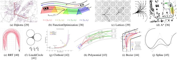
Figure 2 The motion planning method in the literature
Table 1 Classification of Motion Planning Techniques Applied in Different Scenes of Automatic Driving
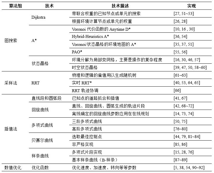
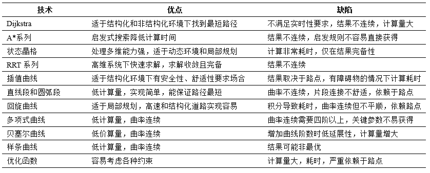
Table 2 Comparison of the advantages and disadvantages of motion planning technology
[Worldwide, motion planning technology promoted by intelligent traffic system research team]
Although the concept of a smart car can be traced back to the 1939 New York World Expo, its implementation took decades. Figure 3 shows the important development nodes of a self-driving car in the form of a timeline.
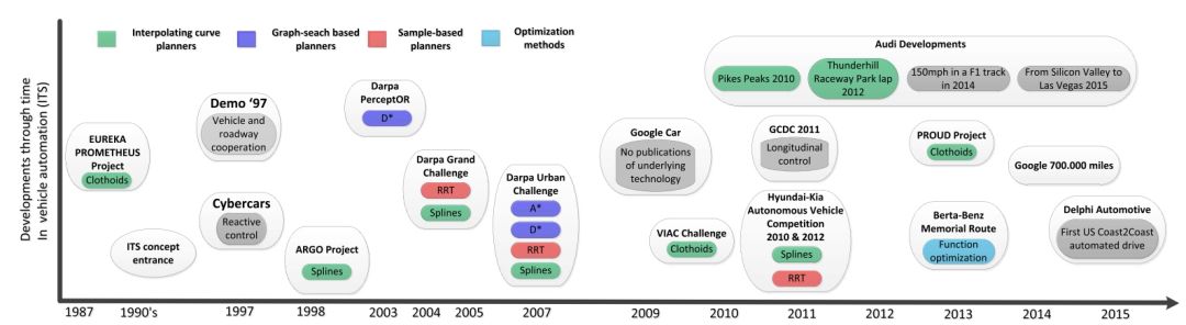
Figure 3 The development of important unmanned vehicles and their motion planning technologies over time
From 1987 to 1994, the Eureka Prometheus project in Europe was the vanguard of smart car research. Among them, different cars from industrial partners such as Daimler and Volvo are self-driving. The path of the bend is implemented with a helix to assist the control system in tracking [14].
In cooperation with General Motors, the PATH project demonstrated its role as a cohort of Demo'97 parts in San Diego, California. The queue is composed of 8 cars driving on a dedicated lane, with a 6-meter spacing. Carnegie Mellon University also participated and demonstrated the Navlab vehicle [113]. In the same year, a report from the Netherlands introduced the CTS service for the first time at Schiphol airport [114], which solved the last mile problem - providing on-site service and on-demand service [115]. In the above system, environmental reaction control and vehicle road coordination are superior to path planning technology.
In the first attempt to route planning technology, VisLab's ARGO is one of them [76]. Based on the vision system, the plan adjusts the fifth-order polynomial spline curve to the lane that the forward-looking camera detects. Later, the DARPA PerceptOR project conducted an autonomous navigation simulation of off-road vehicles [116][117]. It was completed by the DARPA Challenge (Grand and Urban challenge), which promoted the research of automated navigation systems and promoted path planning techniques. Development (as shown in Figure 2).
Since Google's vehicles entered the market in 2009, Google has demonstrated its ability to drive autonomously on many occasions, gaining more than 700,000 miles of accident-free miles. Google is also promoting this technology's legislation, and in May 2012, it obtained the first license for a self-driving vehicle (two months later, Nevada issued the first auto-driving law) [118]. However, there is no announcement of technology in motion planning and control in Google’s automatic driving.
In 2010, the Visual Laboratory International Automatic Driving Challenge (VISC) was held. The vehicle traveled 13,000 km from Italy (Parma) to China (Shanghai) in an automatic mode. The planning is mainly concerned with the cost function of spiral generation. In the same year and 2012, Hyundai Motor launched the Autonomous Vehicle Challenge in Korea. The challenges of the 2010 Challenge are focused on tracking and obstacle avoidance. The challenge of the 2012 competition focused on the understanding of driving scenes in cities and the detection of signal lights [17]. The motion planning techniques involved include spirals [18], [119], RRT [120] and other technologies.
In 2011, the European Collaborative Driving Challenge (GCDC) focused on vertical control development [143]. However, some teams have also developed path planning strategies (eg, AnnieWAY's state grid [131]). The next 2016 GCDC Challenge, horizontal control of the queue, parallel roads and urban road conditions under congested road conditions will also be taken into consideration.
Recently, Audi and Stanford[42][144] developed high-performance vehicle control and achieved spiral curve planning. Participating demos include: the 2010 Pike Peak climb, a lap in Leishan Race Track in 2012, a F1 speed of 150 miles in 2014, and automatic driving from Silicon Valley to Las Vegas in 2015. That is, in 2015, Delphi Autopilot first realized its journey from the US East Coast to the West Coast for 9 days, from San Francisco to New York. Table 3 lists the situation of the international research team.
Table 3 International Intelligent Transportation Systems Research Team

ã€to sum up】
The development of intelligent planning algorithms is a key technology in the field of robotics research [20][21]. Extending to self-driving cars, related constraints include traffic rules, speed, road conditions, and time constraints (planning to designated areas under complex conditions). This article summarizes the motion planning technology of autonomous vehicles from the following two aspects: First, compare and analyze four major types of motion planning techniques (as listed in Table 1), including graph search, sampling method, interpolation method, and numerical optimization method; Second, researched the motion planning algorithms implemented by major intelligent transport system research units worldwide (as listed in Table 3).
The two main algorithms that have been implemented for the research team in recent years are:
1, interpolation method. In recent years, the planning algorithms used in self-driving vehicles include spirals (Audi, Parma/VisLab, Stanford), Bezier curves (INRIA) and polynomial curves (Daimler, INRIA). This is based on the richness of map information in a structured road environment - data that can provide the required road traffic in California. In addition, for the sake of comfort, safety, vehicle geometry and dynamics constraints, the trajectory generation also needs to go through the curve optimization step.
2, the map search. The state grid is one of the most widely used methods, and research institutes such as CMU, KIT, and GMC have realized. When considering the comfort, safety, vehicle geometry and dynamic constraints, the algorithm can quickly search for the optimal path, although the algorithm only has the analytic completeness.
[Future research focus]
The challenge now facing motion planning is real-time planning in a dynamic environment. In the urban road scenario, there are numerous traffic participants (for example, pedestrians, cyclists, other vehicles, etc.), which require continuous evaluation of the planned trajectory. How to achieve multi-dynamic obstacles within a limited time without collision-free trajectory generation in the environment is an unsolved problem. The difficulty lies in the time-consuming perception of the environment [145] which greatly reduces the decision-making window of motion planning. The current implementation of the algorithm is not enough to overcome this limitation.
Since planning is the link between perception and control, the current development of new planning algorithms takes into account perceived uncertainty and control constraints. In the dynamic environment data collection process, the latest development goal of path planning is to correctly handle the uncertainty in the data acquisition process. This will have better context-awareness in real-time situations and guide the planning process. Improve the ability to prevent dangerous situations by considering the uncertainty of the perception phase. From a control point of view, multiple objectives need to be considered, including the kinematic constraints of the vehicle and passenger comfort. In recent years, studies have considered these control constraints through the smoothness and executability of trajectories. The next study may be to consider the control constraints while merging the perceived uncertainty. KIT and CMU have started research in this area.
Another trend is to increase the driver's large control loop, similar to the ADAS function, through the HMI to achieve trajectory interaction with the driver. Under the condition of ensuring the safety, smoothness and execution of the trajectory, perception uncertainty, control constraints, and the integration of driver knowledge will be a new and challenging research.
High efficient charging speed for Lenovo and IBM laptop, stable current outlet can offer power for the laptop at the same time charge the laptop battery. The best choice for your replacement adapter. We can meet your specific requirement of the products, like label design. The plug type is US/UK/AU/EU.The material of these products is PC+ABS. All condition of our products is 100% brand new.
Our products built with input/output overvoltage protection, input/output overcurrent protection, over temperature protection, over power protection and short circuit protection. You can send more details of this product, so that we can offer best service to you!
Lenovo Adapter,Charger For Lenovo,Power Supply For Lenovo,Adapter For Lenovo Mini
Shenzhen Waweis Technology Co., Ltd. , https://www.laptopsasdapter.com