
As a wireless LAN technology, WiMAX has obvious advantages in bandwidth, coverage and data rate compared with current 3G and WIFI, and has the characteristics of low maintenance cost, convenient erection, and low construction cost. For such an emerging and promising wireless communication technology, the institutions and enterprises that have already carried out research and development in China are still generally small. The products that can be seen in the market are basically overseas products, and the price is also high. The development of wireless LAN products is of great significance to promote the development of wireless LAN in China. However, as a new technology, RF technology design is quite difficult, especially in the 5.8G frequency band. It puts high requirements on the linearity of the power amplifier, the noise index of the low noise amplifier, and the phase noise index of the frequency source. We design Based on WiMAX technology 5.8G wireless private network RF system, mainly used 0402 package device placement, and the baseband circuit is convenient.
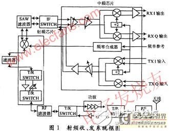
1 RF receiving and transmitting system worksThe function of the RF receiving and transmitting system is to provide a wireless transceiver channel for the baseband I and Q signals. In the transmission time slot, the baseband I, Q signals are mixed twice, one intermediate frequency is fixed at 380 MHz, and the two intermediate frequency local oscillator frequencies are variable, so that the radio frequency works in the desired channel, and the converted RF signal is filtered. After the power is amplified, it is sent by the antenna to the far end; in the receiving time slot, the signal transmitted from the far end received by the antenna is amplified by low noise, and after two times of mixing, under the control of the receiving AGC, the signal is sent to the same amplitude. Baseband processing board.
The RF module is directly connected to the baseband board through a 125-pin socket. The signal connected to the baseband board is transmitted through the 125-pin socket. The RF signal is mounted on the PCB through the MCX connector and directly output to the transceiver antenna.
2.1 Highly integrated chip
The top-level company IF chip and RF chip are selected as the highly integrated solution for this wireless RF system. These chips consist of IF and RF transceivers supporting the 4.9 to 5.9 GHz air interface band. The chipset can work in TDD mode with complex I/Q interface support systems. This highly integrated chip reduces space and not only helps simplify design, but also saves bill of materials (BOM) costs. The low-noise, high-linearity of the IF chip requires only one IF filter. It also includes two IF and RF synthesizers, a high-speed digital variable gain amplifier with a gain control range of 50 dB.
IF chip function: complete the I/Q baseband signal up-conversion to 380 MHz fixed IF signal in the transmission time slot; complete the received 380 MHz fixed IF signal in the receive time slot to down-convert the zero-IF I/Q baseband signal .
RF chip function: In the transmission time slot, the fixed IF signal of 380 MHz is up-converted to the required RF channel frequency; the received RF signal is amplified and down-converted to a fixed IF signal of 380 MHz in the receiving time slot.
2.2 Linear Power Amplifier
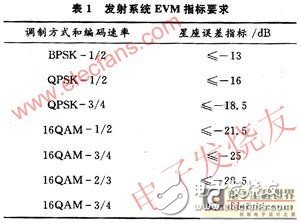
In the digital microwave communication system, the nonlinear distortion of the power amplifier has a great influence on the signal transmission quality. In the high-order QAM modulation system, the third-order intermodulation coefficient of the power amplifier is degraded by 1 dB and the bit error rate will deteriorate by 80%. . In this system, the power reversal method is used to improve the third-order intermodulation coefficient of the system. The power amplifier works 10 dB below the P1dB output power of the final amplifier (considering the insertion loss of the transceiver switch and the RF filter 1.6 dB). When the power requirement is 16 dBm, the P1dB of the final stage amplifier should be at least 28 dBm. We use an efficient linear power amplifier with an EVM of 3% at an output power of 21.5 dBm. This indicator plays a decisive role in the transmitter's emission constellation error index. The EVM specifications for the entire transmitting system are shown in Table 1.
2.3 Receive sensitivity and receive AGC control
Receiver sensitivity is an important technical indicator of the receiving system. For 802.16d systems, the receiver sensitivity can be calculated by the following formula:
Rss=-102+SNRrx+10Log((Fs*200)/256)
For 3.5 MHz bandwidth, here Fs=3.5*8/7
SNRrx is the system demodulation normalized signal-to-noise ratio requirement. For 64QAM-3/4, the normalized signal-to-noise ratio requirement is 24.4 dB.
By calculating Rss = -72.6 dBm.
The relationship between receiver sensitivity and noise figure is satisfied:
Rss=-174 dBm+101g BW+NF
Therefore, to meet the above-mentioned receiving sensitivity requirements, the NF of the receiver must be made sufficiently small under the condition that the bandwidth is determined. The LNA noise factor we chose is better than 1.7dB, which fully meets the requirements of the index.
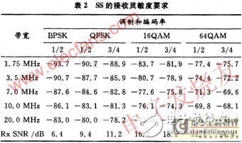
The receiving sensitivity requirements of SS are shown in Table 2 (BER ≤ 10-6).
In the communication system, the receiver uses an automatic gain control (AGC) circuit to improve the dynamic control range of the receiver, so that the strong input signal does not saturate the receiver and generate a large distortion, and the small signal does not make the receiver The demodulator does not detect and is completely lost, which provides the system with appropriate gain and linearity to meet the receiver sensitivity requirements.
In this system, the maximum normal receiving level is not less than -30 dBm, and the system should not be damaged when the receiving system receives an input signal of 0 dBm; the minimum receiving level (that is, the receiver sensitivity when the modulation mode is BPSK) -91 dBm, AGC control range 91 dB. The receive gain control uses a three-stage gain control scheme: the first stage is at the LNA, and the two-stage LNA has a bypass switch function that sets the current to zero and achieves the minimum insertion loss. When receiving a large signal, the bypass mode can adjust the dynamic receiving gain range to more than 26 dB; the second stage has a gain control range of 15 dB in the RF signal at 5.8 GHz; the third stage has a medium frequency of 380 MHz. At the signal, the IF chip has a high-speed digital VGA control with a range of 50 dB.
2.4 Frequency source
Since the RF local oscillator is not a perfect continuous wave single frequency source, but there is phase noise, it will change the input signal at the output of the RF conversion stage. Since the phase of the digital signal carries information, the introduced phase change increases the bit error rate, and the high degree of modulation affects the degree of increase in the bit error rate. For the 64QAM modulation method, the RF output frequency is required to be offset by 1 kHz and the phase noise requirement is -88 dBc/Hz. At the same time, the RF local oscillator frequency drift (ie frequency stability) causes phase error in the demodulation process, resulting in a decrease in the effective signal amplitude and an increase in the bit error rate. The technical specifications of the frequency stability depend on the modulation method used by the system and the user's communication quality. Claim. The system adopts 64QAM modulation mode and requires frequency stability ±1.5 & TImes; 10-6. The frequency stability and phase noise of the frequency source are another key technical indicator of the system. We intend to use the phase-locked phase technique for frequency synthesis, and the reference source is generated by a highly stable crystal.
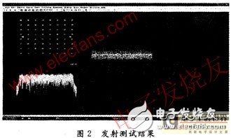
3 test resultsThe test tests various indicators according to the 802.16-based fixed broadband wireless access point-to-point RF technology requirements, using the AGILENT instrument E4438C as the signal source, and the E4440C as the vector signal analyzer. The system has a maximum output power of 18 dBm and a minimum power of less than -50 dBm. The channel bandwidth is chosen to be 3.5 MHz and the transmit EVM is better than -31 dB. The specific indicators are shown in Figure 3. The received signal level is -30 to -91 dBm, and the minimum received signal level is lower than -91 dBm (BPSK modulation).
The 5.8 GHz wireless private network RF system equipment is installed in the two places with the baseband processing equipment. The hop distance is about 10 km. It experiences various bad weather such as heavy rain and fog. The two places are partially blocked, and the equipment works stably and reliably. The error rate of each system is better than 10-7. It can transmit 10~50 Mb/s Ethernet data in both directions, and transmit movie image and sound, and the effect is very good.
PCD Drills
PCD drills used to drill through holes or blind holes in solid materials and to ream holes in existing holes. Commonly used drill bits mainly include twist drills, flat drills, center drills, deep hole drills and nest drills. Although reamer and boring drills cannot drill holes in solid materials, they are customarily classified as drill bits.
Our customers can depend on us for prompt, efficient response and quality products that attest to our expertise in engineering and manufacturing. As part of our scrupulous inspection procedure, we test 100% of our drills .375" and under for assembly integrity, leakage, and specified oil flow.
FEATURE:
1.Hardness PCD blanks more than 5000HV.
2. PCD Stone Milling cutters is maily used for High efficiency milling and depth character engraving on underside, grooving areas with good surface Roughness.
3.Top quality as world leading manufactuers, high abrasive resistance and with long service life.
4.big quantity in stock for ordering
PCD carving tool
PCD drills
Flexible in order quantity:
Samples can be provided before mass production, and MOQ can be discussed accordingly.
PRODUCT DETAIL:


PRODUCTING PROGRESS:

PAYMENT AND DELIVERY:

PRODUCT EQUIPMENT :

ABOUT US :
We are specialize in manufacturing PCD diamond tools and Carbide tools. Our major product inclulde PCD Inserts , PCD Reamers , PCD End Mills, PCD Taps, Cabide Inserts,Carbide Drills, Carbide Reams, Taps etc.,
We also offered customized cutting tools per drawings, and provide package according to customer requirements. We manufacture a series range of cutting tools for machining of Cast iron, Aluminium alloy and Non-Ferros metal, it is widely used in all major sectors like Automobiles, Engineering, Aerospace, Aviation and 3C industry. Premium quality of raw material is used in the production and strict examination during processing with advanced equipment, so our client are satisfied with our reliable quality and on-time delivery.
Our best selling of cutting tools include PCD Inserts, PCD End Mill, PCD Ball Nose Mill, PCD Reamer, Carbide Taps , Carbide End Mill, Special Form Cutter and many more. For these years we have been made a large forward in the technologies of manufacturing cutting tools. With high quality on performance and price, our product sells well both on domestic and overseas market. And we will always focus on the quality and best service, to make long business relationship.

quanlity control:
We have dedicated team of quality control and precise equipment to keep good and stable performance for our products and processing services.

PCD Drill Bit ,PCD Drills,Carbide Drill Bit ,End Mill Bit
OPT Cutting Tools Co., Ltd. , https://www.optdiamondtoolss.com