
Summary:
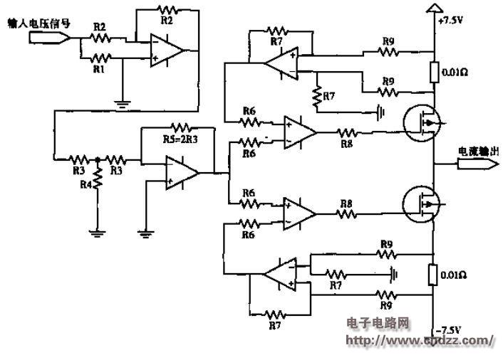
This paper describes the working principle of two kinds of amplifying circuits in the design of the current amplifying module of the signal generating device, and compares their performances. It is concluded that the output signal of the latter circuit is better than that in the case of small current output. The conclusion of the former circuit.
The signal generating device is an integral part of the "multi-function microcomputer protection and substation integrated automation experimental training device" developed by Hunan University. Its main function is to simulate various conventional and fault conditions in the power system and to generate current and voltage signals. In order to simulate the actual situation of the secondary field, the current output signal of the signal generating device must be adjustable from 0 to 30 A (peak), and the output error must be ≤ 0.11. To this end, the designed current amplifying module must meet the requirements of small signal input, high power precision output, and can withstand high current and high voltage. Therefore, in design, in addition to considering the stability of the circuit module, if the external load changes within a certain range, it must also ensure the consistency of the output waveform and the input signal waveform.
Current amplifier circuit design 1
See PDF document for details.
[More items]
Photovoltaic New Energy Magnetic Ring Inductor
Photovoltaic New Energy Magnetic Ring Inductor,Common Mode Toroidal Inductors,High Frequency High Power Inductors,Three-Phase Common Mode Filter Inductor
Shenzhen Sichuangge Magneto-electric Co. , Ltd , https://www.scginductor.com