
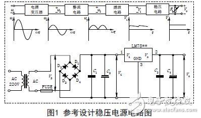
The operation of any electronic device is inseparable from the DC power supply. The normal operation of transistors and integrated circuits requires DC power supply. The methods for providing DC power mainly include dry batteries and regulated power supplies. The dry battery has the advantages of stable output voltage and easy portability, but its short capacity and short life are also obvious. The DC stabilized power supply can convert 220V AC into a steady stream of stable DC. It consists of four parts: transformer, rectifier, filter, and voltage regulator. The reference circuit is shown in Figure 1.
Transforming
The output voltage of the regulated power supply is generally determined according to the needs of the equipment. Some instruments require several different voltages at the same time. The separate regulated power supply can adjust the output voltage within a certain range. When the adjustment range is large, it can be divided into several gear positions. Therefore, it is necessary to convert the alternating current into a voltage of a proper amplitude through a power transformer, and then perform rectification and the like. If necessary, the secondary coil of the transformer generally uses two or more suitable transformers to convert 220V±10% of high-voltage alternating current. To meet the needs of low-voltage AC, to meet the power supply and output voltage requirements, the following principles should be followed:
(1) Reliable and stable output should be ensured at 220V ± 15%. Generally, the DC voltage after transformer transformation, rectification and filtering can be determined as follows:
First, it is necessary to consider the integrated voltage regulator circuit is generally required to minimize the input and output voltage difference; the second is to consider the bridge rectifier circuit to consume two diodes forward voltage drop; the third is to leave a certain margin. Excessive output voltage will increase the amount of heat dissipation, and too low will be unstable when output low voltage, thus determining the DC voltage.
(2) The transformer must retain more than 20% of the current margin.
2. Rectification
The sinusoidal alternating current is converted into pulsating direct current, which is mainly realized by the unidirectional conduction principle of the diode, and the rectifier circuit can be divided into half wave rectification, full wave rectification and bridge rectification. The power supply mostly uses a bridge rectifier circuit, and the bridge rectifier consists of four diodes. Each diode operates with two parameters:
First, the current needs to meet the load current of the power supply. Since the four diodes in the bridge rectifier circuit work alternately every two, the operating current of each diode is half of the load current; the second is the reverse withstand voltage. The reverse voltage is greater than the maximum possible peak.
(1) Current load ID? I1
(2) Reverse withstand voltage is the peak value of the highest output of the transformer VD" V2.
3. Filtering
The function of the filtering is to filter the pulsating DC into a DC voltage containing a certain ripple, and a device such as a capacitor or an inductor can be used. In practice, a large-capacity electrolytic capacitor is often used for filtering.
In the figure, C2 and C4 are low-frequency filter capacitors. According to the relevant formula in the experimental principle and the change of the power grid, the capacitance and withstand voltage value can be designed and calculated. The nominal value and withstand voltage value of the capacitor and the capacitor model are selected. Choose from a few hundred to a few thousand microfarads).
C1 and C3 are high frequency filter capacitors for eliminating high frequency self-excitation to make the output voltage more stable and reliable. Usually in the range of 0.01μF to 0.33μF.
(1) The withstand voltage of the low-frequency filter capacitor should be greater than the highest voltage in the circuit, and a certain margin must be left;
(2) The selection of low-frequency filter capacitor C2 should satisfy: C2≥RL1(3~5)2T;
RL is the load resistance and T is the period of the input AC. For the filter capacitor after the integrated voltage regulation, hundreds of micro-methods can be selected as appropriate;
(3) The low-frequency capacitor C 2 can also determine the capacity of the rectified filter capacitor according to the value of the load current, namely:
C2 ≥ (IL / 50mA) & TImes; 100uF.
4. Voltage regulation
The rectified and filtered DC voltage is an unstable DC voltage that contains ripple and changes with fluctuations in the AC supply voltage and load. Unstable voltage can cause unstable operation of the equipment, sometimes not even normal. jobs. For this reason, a voltage stabilizing circuit is added after filtering to ensure the smoothness of the output voltage. The voltage regulation method has a voltage stabilizing circuit composed of discrete components and an integrated voltage stabilizing circuit.
The voltage stabilizing circuit composed of discrete components has series voltage regulation, shunt voltage regulation and switching type voltage regulation, among which the series voltage regulation mode is more commonly used.
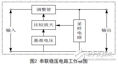
(1) series regulator circuit
The working block diagram of the series regulator circuit is shown in Figure 2. It consists of a sampling circuit, a reference voltage circuit, a comparison amplifier circuit and an adjustment circuit.
(2) Integrated voltage regulator
With the widespread use of integrated process technology, the voltage regulator circuit is also integrated on a chip, called a three-terminal integrated voltage regulator, which has the advantages of safe, reliable, convenient and low price.
Three-terminal regulators can be divided into four categories according to the output voltage mode:
1 fixed output positive voltage regulator 7800 series, such as 7805 voltage regulator value is +5V.
2 fixed output negative regulator 7900 series.
3 adjustable output positive regulator LM 1 1 7, LM 2 1 7, LM317 and LM123, LM140, LM138, LM150 and so on.
4 adjustable output negative regulator LM 1 3 7, LM 2 3 7, LM337 and so on.
5. DC stabilized power supply generally must be equipped with insurance and heat sink
Insurance is an important device used to ensure the safe operation of the power supply. The insurance can automatically cut off the circuit when the power output is short-circuited or overloaded, thus ensuring the safety of the power supply. The heat sink function is to dissipate the integrated voltage regulator circuit to ensure that the temperature of the integrated regulator does not exceed the standard value.
3G Antenna,3G outdoor antenna,3G indoor antenna
Yetnorson Antenna Co., Ltd. , https://www.xhlantenna.com