
The automobile air conditioning system is a special device for realizing the adjustment of the air environment in the vehicle to meet the requirements of the passengers in the vehicle for the comfort of the ride [1]. The comfort of the occupants in the car is related to the relative humidity of the air inside the car, the temperature and the air flow rate and the surface temperature of the items inside the car [2]. Therefore, the car air conditioning system needs to perceive various environmental parameters inside and outside the car, and adjust accordingly according to requirements. The automobile air conditioning system is affected by factors such as vehicle space and vehicle working conditions, and the working environment is in a harsh environment and the working load is large, so the anti-interference and stability requirements of the control system are high. Conventional automotive air conditioning systems are controlled manually or automatically, and the control lines of these control methods are wired. Due to the many air-conditioning control functions, the system control circuit is complicated, the control precision is also low, and the disadvantages such as high cost, complicated monitoring system and poor anti-interference are caused, so the feasibility and control accuracy of the air-conditioning control system are still greatly affected. .
This article refers to the address: http://
ZigBee technology [3] is an emerging intelligent sensor and control technology. It is a combination of sensor technology and wireless network technology, and is widely used in environmental monitoring and industrial control. Because of its low cost, small size, strong real-time performance, low power consumption, strong anti-interference, and good embedding [4], it is especially suitable for the work site, the data transmission is small, the real-time performance is strong, and the transmission distance is short. And the wiring is not convenient. In the automotive air conditioning control system, the ZigBee technology is used to collect and transmit the environmental parameters of the air conditioning system, and the transmission and control signals are controlled to avoid the interference and influence of the harsh industrial site environment on the wired transmission mode (such as electromagnetic interference, humidity, vibration). Etc.), improve the reliability and anti-interference ability of the control system, and have certain significance for reducing the energy consumption of the car air conditioning system and improving the passenger comfort.
This paper combines the requirements of automobile for air conditioning system, and designs a ZigBee-based automotive air conditioning control system, which greatly reduces the cost and complexity of the control system, reduces the energy consumption of the system, and improves the system control accuracy and feasibility.
1 system design
1.1 Control system design
The principle of the automobile air conditioning control system is shown in Figure 1. The system consists of a sensor node, a system main control node, and an action node. The sensor nodes include nodes such as temperature and humidity sensors inside the vehicle, temperature sensors outside the vehicle, CO2 concentration sensors, illumination sensors, and various damper sensors. The motion control node has various damper control nodes such as a compressor control node, a blower control node, a defroster damper, a hybrid damper damper, a warm water valve, and a humidifier control node. The system will process the monitored temperature, humidity, CO2 concentration and other internal and external environment data through the processing of the sensor node, convert it into a digital signal and send it to the main control node, and the main node will perform corresponding processing, and then deliver the corresponding command to the action node. To control the temperature, humidity and air quality in the car within the set range.
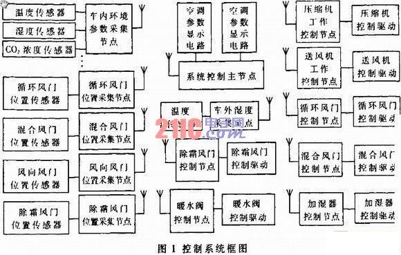
In the system design, the system network structure is a star topology, the system main control node is the network controller, and the other nodes are slave nodes. The network topology is shown in Figure 2. The master node is set to a full function node (FFD), which is responsible for system management and control; the sensor and control nodes are set to simplify function nodes (RFD), responsible for environmental parameter data acquisition and air conditioning system control.

1.2 System circuit design The circuit design of automotive air conditioning control system includes: (1) environmental data acquisition circuit, including vehicle temperature, humidity and CO2 concentration acquisition node, illumination collection node, vehicle temperature collection node, damper position detection node, etc. (2) Air conditioning system operation and control circuit, including compressor work control node, evaporator and condenser fan control node, damper position control node, defrosting control node, humidification control node, heating control node, etc.; (3) main The control node circuit mainly includes a control and display circuit, an operation control circuit and the like.
The basic circuit of the vehicle interior environment parameter sensor is shown in Figure 3. The sensor circuit is composed of a CO2 concentration sensor and a signal amplifying circuit, a temperature and humidity sensor, a power supply circuit, and a CC2430 processor. The supply voltage is 5 V and 3 V, respectively. The CO2 concentration detection uses the TGS4161 sensor, which has the characteristics of small size, long life, good selectivity and stability, and also has high humidity resistance and low temperature resistance. It can be widely used in automatic ventilation system or CO2 gas. Long-term monitoring and other applications [5]. The weak voltage output from the CO2 sensor is amplified by amplifier U3 (LM386) and output to P0_2 of U5 for A/D conversion and stored in the memory unit specified by CC2430. PR1 adjusts the gain of the amplifier so that the concentration output signal voltage varies between 0 and 3 V. In order to keep the sensor at the most sensitive temperature, it is necessary to provide a heating voltage to the heater for heating.
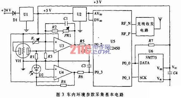
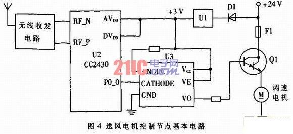
The temperature and humidity detection uses the digital temperature/humidity sensor SHT75[6] (U6), which has the characteristics of small size, simple and reliable, low price, digital output, no debugging, no calibration and strong interchangeability. The converter and memory automatically calibrate the relative humidity during the measurement process. The DATA and SCK pins of U6 are connected to the P0_0 and P0_1 pins of U5 respectively. The PCK of U5 controls the SCK pin of U6, and it is decided to read the temperature or humidity data from the memory of U6, and then store the temperature/humidity parameters to The storage unit specified by CC2430. The illuminance detection uses an illuminance measuring circuit composed of a photodiode, and the photosensitive element D1 is input to the P0_3 of U5 via the U4 amplifier for A/D conversion. The basic circuit of the evaporator, condenser, ventilation fan motor and compressor control node is shown in Figure 4. After receiving the control signal of the main controller, U2 calls the motor speed control interrupt program in the processor, and outputs a certain duty control signal from P0_0 via the photocoupler U3 to control the conduction current of Q1, thereby controlling the air supply. The speed of the motor.
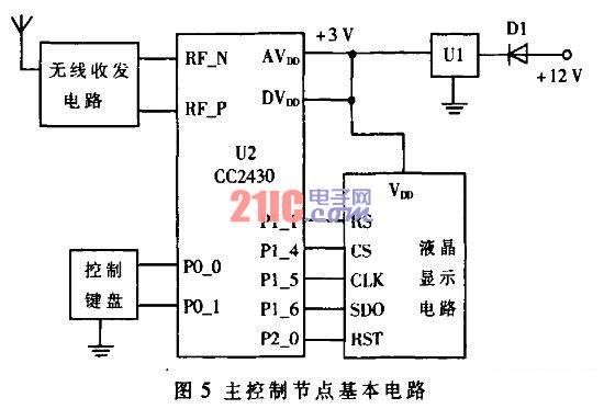
The main control node circuit of the system is shown in Figure 5. The circuit is mainly composed of the main node processor, control buttons and parameter display circuits.
2 system software design
2.1 Network Protocol and Data Frame Design
Through the analysis of the application of this system, in order to save the program storage space of the node, the ZigBee protocol has been streamlined. The security mechanism is omitted in the system protocol. The device type of the FFD node is set to the non-security mechanism full function node (FFDNS[5]), and the device type of the RFD node is the no security mechanism simplified function node (RFDNS), and the system node is Primitives not related to this application are omitted to improve protocol efficiency. The sensor and control node protocol and implementation primitives are shown in Figure 6.

The data frame format of system data transmission uses ZigBee's MAC layer packet format [6], and its structure is shown in Figure 7. The frame payload in the data packet is defined as: slave node number + node type + detection parameter (or action instruction), where the slave node number is bound to the sensor or control node ID.
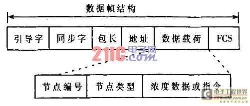
Figure 7 digital frame structure
2.2 system software design
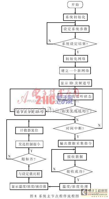
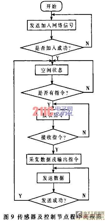
The control system programming uses a modular programming method consisting of a main control module and a wireless node module. The system software flow is shown in Figure 8, and the wireless network node flow chart is shown in Figure 9.
[next]
3 system test results and discussion
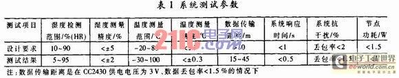
After the design of each node of the system is completed, the system designed in this paper is tested in a model of the bus, and the test results are shown in Table 1. The test results show that the parameters of the system meet the requirements. Since there are various electromagnetic interferences at the working site of the system, corresponding anti-interference measures need to be taken at each node. For example, the system power supply adopts corresponding anti-interference measures.
As an emerging monitoring technology in recent years, wireless sensor networks are widely used in industrial automatic process control. The ZigBee wireless sensor-based automotive air conditioning control system designed in this paper has the characteristics of low cost, reliable operation, strong real-time performance and low wiring. It improves the feasibility and stability of the operation of the automotive air conditioning control system, improves the control accuracy and reduces the air conditioning. System energy consumption has a certain meaning. ZigBee-based air conditioning control system has a good application prospect in automotive air conditioning systems due to its low cost, good real-time performance and strong embedding.
High Voltage STA Armored Cable
High Voltage STA Armored Cable is a type of Power Cable that is designed to carry high voltage electricity in a safe and efficient manner. It is commonly used in industrial and commercial applications where high voltage power is required for heavy machinery and equipment.
The cable is constructed with a solid or stranded copper conductor, which is insulated with a high-quality material such as XLPE or EPR. The insulation provides excellent electrical properties, such as high dielectric strength and low capacitance, which ensures that the cable can handle high voltage without any breakdown.
The cable is then wrapped with a layer of galvanized steel tape armor, which provides mechanical protection against external damage, such as impact and abrasion. The armor also helps to prevent the cable from being damaged by rodents and other animals.
Finally, the cable is covered with a sheath made of PVC or PE material, which provides additional protection against moisture, chemicals, and other environmental factors. The sheath also makes the cable more resistant to fire, which is important in industrial and commercial settings.
Overall, High Voltage STA Armored Cable is a reliable and durable solution for carrying high voltage power over long distances. It is available in a range of sizes and specifications to meet the specific needs of different applications.
PVC Sheathed Electric Cable,Copper Conductor Power Cable,High Voltage Xlpe Power Cable,High Voltage XLPE Insulated STA Armoured Power Cable,STA Armour High Voltage XLPE Cable
Ruitian Cable CO.,LTD. , https://www.rtlinecable.com