
The first section of hand soldering tools
Any electronic product, from a rectifier composed of several parts to a computer system composed of thousands of components, is composed of basic electronic components and functions, and is connected by a certain process according to the working principle of the circuit. Although there are many connection methods (eg, wrap, crimp, bond, etc.), the most widely used method is soldering.
1. Hand soldering tools
(1) Electric iron
(2) chrome frame
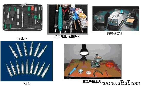
figure 1
2. Conditions of soldering
In order to improve the quality of welding, it is necessary to pay attention to the conditions of soldering.
The weldment must be weldable.
The surface of the metal to be welded should be kept clean.
Use a suitable flux.
Have the proper soldering temperature.
Have the right welding time. Section 2 Solder and Flux
1. Welding material
Any metal or alloy used to fuse two or more metal faces to make them a whole is called solder. The solder mentioned here is only for the solder used for soldering.
Common soldering materials:
Tubular solder wire
Anti-oxidation solder
Silver-containing solder
Solder paste 2. Selection of flux.
During the soldering process, a thin layer of oxide film is generated due to the heating of the metal, which will hinder the solder infiltration, affect the formation of the solder joint alloy, and easily lead to the phenomenon of soldering and false soldering. The use of flux improves weldability. The flux has rosin, rosin solution, solder paste soldering oil, etc., which can be reasonably selected according to different welding objects. Solder paste soldering oil and the like have certain corrosive properties and cannot be used for soldering electronic components and circuit boards. After soldering, the solder paste soldering oil remaining in the soldering station should be wiped clean. Rosin should be used as flux when tinning the component leads. The printed circuit board is coated with a rosin solution, and the components do not need to be soldered when soldered.
The third section of the manual soldering precautions
Manual tin welding technology is a basic skill, that is, in the case of large-scale production, maintenance and repair must also use manual welding. Therefore, you must be proficient in learning and practicing practice. The notes are as follows:
1. Hold the chrome iron posture and master the correct operation posture to ensure the operator's physical and mental health and reduce labor injuries. In order to reduce the harm of chemical substances volatilized by the flux during heating and reduce the inhalation of harmful gases, in general, the distance from the soldering iron to the nose should be no less than 20cm, usually 30cm.
There are three ways to solder the soldering iron, as shown in Figure 2.
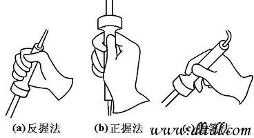
Figure 2 shows the method of holding the soldering iron
The anti-grip method is stable, long-term operation is not easy to fatigue, and is suitable for the operation of high-power soldering iron; the positive grip method is suitable for the operation of medium-power soldering iron or electric iron with elbow; welding parts such as printed boards are generally welded on the operation table. When using the pen method.
2. Solder wire is generally used in two ways, as shown in Figure 3. Since the solder wire contains a certain proportion of lead, which is a heavy metal harmful to the human body, it is necessary to wear gloves or wash hands after handling to avoid ingesting lead dust.
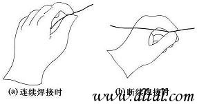
Figure 3: How to take solder wire
3. After the soldering iron is used, it must be placed securely on the soldering iron frame, and pay attention to other impurities such as wires and wires. Do not touch the soldering iron tip to avoid scalding the wires and causing electric leakage and other accidents.
The basic steps of the fourth section of manual welding operations
Master the soldering iron temperature and soldering time, and choose the proper soldering iron tip and solder joint contact position to get a good solder joint. The correct manual soldering process can be divided into five steps, as shown.
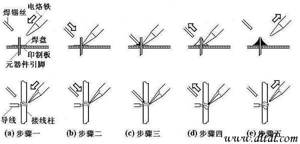
Figure 4 manual welding steps
1. Basic operation steps
(1) Step 1: Prepare for welding (figure (a))
Hold the wire in the left hand and hold the soldering iron in the right hand to enter the ready-welded state. The tip is required to be clean, free of oxides such as slag, and coated with a layer of solder on the surface.
(2) Step 2: Heating the weldment (figure (b))
The tip of the soldering iron is placed at the junction of the two weldments to heat the entire weldment for approximately 1 to 2 seconds. For soldering components on a printed board, care should be taken to allow the soldering iron tip to simultaneously touch two soldered objects. For example, the wires in Figure (b) and the terminals, component leads and pads should be uniformly heated at the same time.
(3) Step 3: Feed the welding wire (Fig. (c))
When the welding surface of the weldment is heated to a certain temperature, the solder wire contacts the weldment from the opposite side of the soldering iron. Note: Do not send the solder wire to the soldering iron!
(4) Step 4: Remove the welding wire (figure (d))
When the wire melts a certain amount, immediately remove the wire from the upper left 45°.
(5) Step 5: Remove the soldering iron (Figure (e))
After soldering the solder pad and the soldering portion of the soldering piece, remove the soldering iron to the upper right 45° direction to end the soldering. From the third step to the end of the fifth step, the time is also about 1 to 2 s.
2. Soldering three-step operation method
For weldments with low heat capacity, such as the connection of thinner wires on the printed board, it can be simplified to a three-step operation.
Preparation: Same as step one above;
Heating and wire feeding: The wire is placed after the tip is placed on the weldment.
Remove the wire soldering iron: After the solder has wetted and spread on the welding surface to the expected range, immediately remove the wire and remove the soldering iron, and note that the time to remove the wire must not lag behind the time to remove the soldering iron. For the low-heat-welding weldment, the whole process takes only 2 to 4 seconds. The rhythm control of each step, the accurate mastery of the sequence, and the skillful coordination of the movements are all problems that can be solved through a lot of practice and hard work. Some people have summed up the control time in a five-step operation method: the soldering iron contacts the solder joints after the first and second (about 2 s), after feeding the wire three or four, remove the soldering iron, the wire melting depends on observation Decide. This method can be referred to, but due to the factors such as the power of the soldering iron and the difference in the heat capacity of the solder joint, there is no rule to grasp the actual welding heat, and specific conditions must be taken. Imagine that for a solder joint with a large heat capacity, if a soldering iron with a small power is used for soldering, the soldering temperature may not be melted during the above-mentioned time, and soldering is impossible.
Section 5: Specific methods of manual welding operations
Under the goal of ensuring high-quality solder joints, the specific welding operation methods can be different, but the methods summarized by the previous ones are not negligible for beginners.
Keep the tip clean
When soldering, the soldering iron tip is in a high temperature state for a long time, and it is exposed to weakly acidic substances such as flux, and its surface is easily oxidized and stained with a black impurity. These impurities form an insulating layer that hinders heat transfer between the tip and the weldment. Therefore, be careful to wipe the tip with a damp cloth or a wet lignocellulosic sponge. For ordinary soldering iron tips, the surface oxide layer can be repaired with a trowel when the corrosion is severe. For long life tips, this method must not be used.
Increase heat transfer by increasing contact area
When heating, the parts of the weldment that require solder infiltration should be evenly heated, instead of just heating a part of the weldment, and do not use a soldering iron to increase the pressure on the weldment to avoid damage or hidden danger. Some beginners use a soldering iron to apply pressure to the welding surface in an attempt to speed up the welding. This is not correct. The correct way is to use different soldering iron tips according to the shape of the weldment, or to trim the soldering iron head yourself, so that the soldering iron head forms a surface contact with the weldment instead of a point or line contact. In this way, the heat transfer efficiency can be greatly improved.
Heating depends on the solder bridge
In non-pipelined operations, the shape of the solder joints is varied and it is unlikely that the tip will be constantly replaced. To increase the efficiency of heating, a solder bridge for heat transfer is required. The so-called solder bridge is to retain a small amount of solder on the soldering iron tip as a bridge for heat transfer between the soldering iron tip and the weldment. Since the thermal conductivity of the molten metal is much higher than that of air, the weldment is quickly heated to the soldering temperature. It should be noted that the amount of tin used as a solder bridge cannot be retained too much, not only because the solder remaining on the soldering iron tip for a long time is in an overheated state, but the quality has actually been lowered, and a misconnection between the solder joints may be caused.
The iron is evacuated
The withdrawal of the soldering iron should be timely, and the angle and direction of the evacuation are related to the formation of the solder joint. The effect of the different withdrawal directions of the soldering iron on the amount of solder joints is shown in the figure.
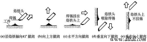
Figure 5 Relationship between the direction of soldering iron withdrawal and the amount of solder joint tin
Cannot move before the solder solidifies
Do not move or subject the weldment to vibration. Especially when clamping the weldment with tweezers, be sure to wait for the solder to solidify before removing the tweezers. Otherwise, the weld structure may be loose or soldered.
The amount of solder should be moderate
A tubular solder wire commonly used for hand soldering, which is internally filled with a flux made of rosin and an activator. The diameter of the solder wire is 0.5, 0.8, 1.0, ..., 5.0mm and other specifications, which should be selected according to the size of the solder joint. Generally, the diameter of the solder wire should be slightly smaller than the diameter of the pad.
As shown in the figure, the excess solder not only consumes the solder unnecessarily, but also increases the welding time and reduces the working speed. More seriously, excessive solder can easily cause an undetectable short circuit fault. Too little solder also does not form a strong bond, which is also disadvantageous. In particular, when the printed printed circuit board leads the lead wire, the amount of solder is insufficient, and the wire is easily detached.
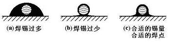
Figure 6 Mastering the amount of solder joints
Flux should be moderate
The right amount of flux is very beneficial for soldering. Excessive use of rosin flux, it is necessary to wipe off excess flux after welding, and prolong the heating time, reducing work efficiency. When the heating time is insufficient, it is easy to form a defect of "slag inclusion". When the switch or connector is soldered, excess flux easily flows to the contacts, which may cause poor contact. The proper amount of solder should be that the perfume can only wet the part where the solder joint will be formed and will not flow through the through hole on the printed board. For the welding using the rosin cored wire, it is basically unnecessary to apply the flux. At present, the printed board production plant has mostly been treated with pine perfume before the circuit board leaves the factory, no need to add flux. >Do not use a soldering iron tip as a tool to transport solder
Some people are used to soldering on the soldering surface, resulting in oxidation of the solder. Because the temperature of the soldering iron tip is generally above 300 °C, the flux in the solder wire is easily decomposed and failed at high temperature, and the solder is also in a low quality state of overheating. In particular, it should be noted that in some old books, the method of transporting solder with a soldering iron tip has been introduced. Please pay attention to the identification.
Section 6 Solder Joint Quality and Inspection
The quality requirements for solder joints should include good electrical contact, mechanical bonding and aesthetics. The most important point in ensuring the quality of solder joints is that they must avoid solder joints.
1. Causes and harms of virtual welding
The virtual welding is mainly caused by oxides and dirt on the surface of the metal to be welded. It makes the solder joints have a connection state with contact resistance, which causes the circuit to work abnormally, and there is an unstable phenomenon when the connection is good and bad, and the noise increases without Regularity brings serious hidden dangers to the debugging, use and maintenance of the circuit. In addition, there are also some solder joints that remain in contact for a long period of time at the beginning of the circuit operation, so it is not easy to find. However, under the influence of environmental conditions such as temperature, humidity and vibration, the contact surface is gradually oxidized, and the contact gradually becomes incomplete. The contact resistance of the solder joint causes local heat generation, and the local temperature rise causes the solder joint condition of incomplete contact to further deteriorate, and finally the solder joint is even peeled off, and the circuit is completely unable to work normally. This process can sometimes be as long as one or two years. The principle can be explained by the concept of “primary batteryâ€: when the solder joint is wetted, water vapor penetrates into the gap, the water molecules dissolve metal oxides and dirt to form electrolyte, and the solder joint The copper and lead-tin solder on both sides are equivalent to the two electrodes of the primary battery, the lead-tin solder loses electrons to be oxidized, and the copper material is reduced. In such a galvanic cell structure, metal loss corrosion occurs in the virtual solder joint, and the local temperature rise exacerbates the chemical reaction, and the mechanical vibration causes the gap therein to continuously expand until the vicious cycle finally causes the virtual solder joint to eventually form an open circuit.
According to statistics, nearly half of the faults in electronic products are caused by poor soldering. However, it is not easy to find the faulty solder joint from an electronic device with thousands of solder joints. Therefore, the virtual soldering is a major hidden danger of circuit reliability and must be strictly avoided. Pay special attention when performing manual soldering operations.
In general, the main causes of solder joints are: poor solder quality; poor reductive flux or insufficient amount of solder; the surface of the soldered surface is not cleaned beforehand, tin plating is not strong; the temperature of the soldering iron tip is too high or too low, There is an oxide layer on the surface; the welding time is not well mastered, too long or too short; when the solder has not solidified during welding, the welding elements are loose.
2. Requirements for solder joints
Reliable electrical connection
Sufficient mechanical strength
Clean and tidy appearance 3. Formation and appearance of typical solder joints
On single-sided and double-sided (multi-layer) printed circuit boards, the formation of solder joints is different: see, on a single panel, solder joints are only formed over the pads on the soldered surface; but in double-panel or On the multi-layer board, the molten solder not only wets the top of the pad, but also penetrates into the metallized hole due to capillary action. The area formed by the solder joint includes the soldering pad, the metallized hole and the component surface. Disk as shown.
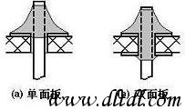
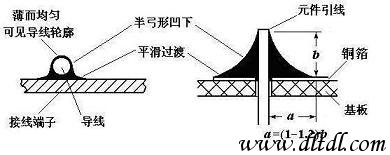
Figure 7: Formation of solder joints Figure 4-10 Appearance of typical solder joints
Referring to the figure, looking at a typical solder joint from the outside, the requirements for it are:
The shape is approximately conical and the surface is slightly concave, and it is in a diffuse shape, centered on the welded wire, and symmetrically formed into a skirt shape. The surface of the virtual solder joint tends to bulge outward and can be identified.
On the solder joint, the solder joint surface is concave and natural transition, the junction between the solder and the weldment is smooth, and the contact angle is as small as possible.
The surface is smooth and has a metallic luster.
No cracks, pinholes, slag inclusions.
Shaded Pole Motor,Capacitor Motor Yc Series,Capacitor Motor Tl61,Shaded Pole Ac Motor
Wentelon Micro-Motor Co.,Ltd. , https://www.wentelon.com