
In the daily tests of engineers, troubleshooting is a common practice, and senior engineers are often able to quickly locate problems. This is closely related to the rich daily experience and flexible use of measuring instruments. The following sections will be analyzed in detail with examples.
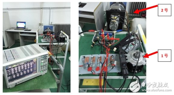
Test siteThe test is for a small motor system. The system is divided into three parts: drive, motor platform, and test. The output of the drive is connected to the motor platform through a cable. The torque sensor is mounted on the motor shaft. All the connecting wires of the sensor are led to the test instrument, and the sensor output signal is connected to the power analyzer motor measuring unit torque BNC interface. The sensor output 100 kHz ± 50 kHz pulse corresponds to 0 ± 5 Nm torque.
This is a daily test site where engineers need to measure basic electrical parameters, find interference problems through waveforms, and evaluate three-phase unbalance.
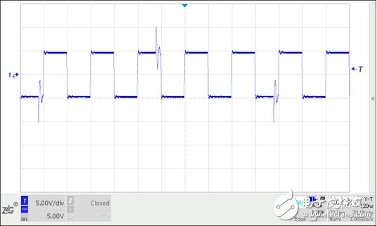
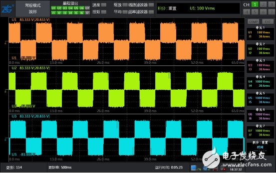
During commissioning, it was found that the drive was powered on but the output was not turned on, and the motor shaft was in a free-standing state, and a large value was measured. Using an oscilloscope to measure the sensor output, it was found that some spikes occurred every few cycles on the 100 kHz pulse, and some pulses were added after the comparator, resulting in a frequency measurement higher than 100 kHz. So where does the interference signal come from? The first suspect is the driver, the driver's power-off interference disappears. Pull the sensor cable out of the sensor, 100 kHz and no interference. Prove that the interference is generated by the driver and coupled to the power analyzer through the driver output line, motor, torque sensor, and wiring.
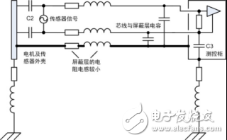
This driver is special, the internal switch tube is still in working state when the inverter is not output, which is much more disturbing than other inverters. The noise model is analyzed as shown in the figure below. The driver outputs the common mode voltage. There is a parasitic capacitance C1 between the winding and the casing. The casing and the sensor circuit have a parasitic capacitance C2 to form a conduction path. The motor and the sensor housing are grounded as the intermediate conductor. However, the distance between the driver, the motor and the measuring and controlling cabinet is long, the impedance of the grounding wire is high, and the potential of the intermediate conductor is not zero. There is still a high-frequency common mode current entering the PA through the cable. The PA torque input is a BNC type terminal. The internal circuit has some space stray capacitance C3 (about several tens of pF). The common mode voltage generates an asymmetrical current on the two signal lines, which is converted into a difference in line impedance. The mode voltage is superimposed on the normal signal.

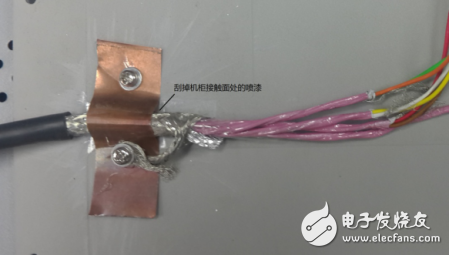
From the perspective of safety, all three cabinets must be connected to the ground, and the strong electric lines are separated from the signal lines to avoid interference. These are the basic principles to be followed. The actual position between the cabinets is far away, and the grounding does not improve much for high-frequency interference, but only as a safety measure. The general consideration for solving such problems is to start from three sources: interference sources, propagation paths, and sensitive devices. The driver and power analyzer are molded devices, which are not easy to change. Consider starting from the propagation path, using a multi-core shielded cable to connect the torque sensor to the measurement and control cabinet. The sensor end shield is connected to the sensor housing and is also connected to the motor platform. The other side The shielding layer is connected to the measuring and controlling cabinet casing. Initially, the shield was connected to the measurement and control cabinet through a long wire. It was found that it did not improve. Finally, the entire wire was pressed into the cabinet with copper, and the interference was greatly attenuated.
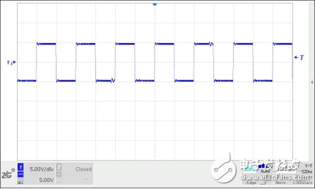
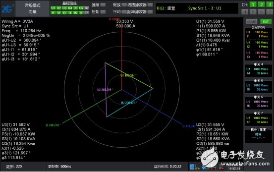
At this point, the system is running and verified again by the power analyzer's data and waveforms. The voltage waveform and vector are perfect.
By the way, the propagation of the interference signal can be propagated through space or conductor. The spatial interference can be divided into induction and radiation, and the radiation is usually transmitted by electromagnetic waves. The induction occurs in a relatively close distance. If the interference source is high voltage and small current, the electric field interference is dominant, and the low voltage and large current are mainly magnetic fields. For sensitive equipment, high-impedance nodes are susceptible to electric field interference, and electric field shielding should be used to shield the conductor from grounding. Low-impedance closed loops are susceptible to magnetic field interference and should minimize loop area. Conducted interference propagates through the device or line in common mode or differential mode. If the device or line is unbalanced, the common mode is converted into a differential mode signal superimposed on the wanted signal.
This example is based on conducted interference, and the method used solves the problem based on the following reasons.
1) A low impedance is applied to the high-frequency signal through the wide shielding layer, and the ground potential difference between the motor platform and the measuring and controlling cabinet is reduced, and the interference current is discharged to the measuring and controlling cabinet through the shield layer of the lower impedance instead of the signal line.
2) Why does it take a length of wire to connect the shield to the measurement cabinet but does not improve the noise? The 0.75 mm2 round wire used in the test was about 50 cm long, which increased the impedance of the wire due to the skin effect.
3) The shielding layer and the core wire form a capacitor through the insulating medium, and the shielding layer is directly connected to the casing, and the effect is equivalent to the core-through capacitor, and the common mode voltage on the core line is bypassed by the capacitor.
4) Here, the motor platform and the measurement and control cabinet are grounded, and the two are connected through the shielding layer of the sensor connection line to form a ground loop. However, in actual engineering applications, the ground loop often inevitably exists. In this example, if there is no shielding layer, the high-frequency ground loop will still be generated through C2, cable and C3. From this aspect, the shield layer changes the loop path.
The method of this paper is for reference only, and the specific problem should be analyzed and verified. Grounding and shielding are very complex subjects. Considering the non-ideal characteristics of real devices, such as the actual one wire can not be equated with the wiring on the circuit schematic, so the theoretical analysis of the noise interference in the system requires careful And actual verification to determine the appropriate layout connection.
The fault interference troubleshooting example fully demonstrates that it is very important to be able to use the power analyzer for testing and rich on-site troubleshooting experience. The power analyzer has powerful waveform and test functions, which can provide high development and production for motors and drives. Reliability test analysis data.
Tv Socket,Tel Socket,Lan Socket,Computer Socket
Wenzhou Niuniu Electric Co., Ltd. , https://www.anmuxisocket.com