
With the continuous development of CAN technology, its application field is not limited to automobile manufacturing, but has also been widely used in industrial equipment, industrial automation and other fields. However, the industrial site environment is harsh and electromagnetic interference is serious. How to ensure the reliability of CAN bus communication is particularly important. This paper focuses on the electromagnetic compatibility of CAN bus, and proposes several measures to improve the electromagnetic compatibility of CAN bus.
First, CAN bus electromagnetic compatibility performance analysis
Electromagnetic compatibility performance has a great impact on the operational reliability of the CAN bus system. At present, in the design of electronic products, the electromagnetic compatibility EMC performance has a great impact on the system, which is related to its normal and stable operation. Internationally, it has begun to impose mandatory restrictions on the electromagnetic compatibility of electronic products. Electromagnetic compatibility has become one of the important indicators for evaluating the performance of products, so it must be taken seriously. Electromagnetic compatibility mainly includes two aspects, one is that the product itself has a bad electromagnetic interference EMI effect, called electromagnetic interference emission; the other is the sensitivity to external electromagnetic signals, called electromagnetic sensitivity EMS. Interference sources, coupling paths and sensitive devices are the three elements of electromagnetic compatibility and are indispensable. The coupling path of electromagnetic interference signals is both conducted and radiated.
Second, measures to improve the electromagnetic compatibility of CAN bus
When non-shielded wires are used, the electromagnetic compatibility of the physical layer becomes very important, and measures for improving electromagnetic compatibility can be classified into three types: emission protection, absorption protection, and conduction protection.
Emission protection - improve the electromagnetic compatibility of electronic devices themselves
Improving the electromagnetic compatibility of electronic devices is an effective measure to fundamentally improve the electromagnetic compatibility of the system. Printed circuit boards (PCBs) are the core components of electronic devices, and their electromagnetic interference resistance and electromagnetic radiation performance are often Interconnected, so the following measures can be taken to improve the electromagnetic compatibility of printed circuit boards.
Select components with good electromagnetic compatibility
Choose components with good EMC performance and try to choose a surface mount package. Proper layout of the device, put the related devices as close as possible, so that the leads between the components are as short as possible. In particular, the clock source crystals of the microcontroller and CAN controller must be placed as specified, otherwise they will not vibrate.
Reasonable layout, reducing ground impedance
Reasonable layout includes three aspects. On the one hand, the position of the components is rationally arranged, and the components associated with each other are arranged as much as possible, so that the leads between each other are as short as possible: the second aspect is to use electronic devices. The internal digital circuitry is effectively separated from the analog circuitry to prevent signal interference between each other. The third aspect is to properly lay out the ground line. Under ideal conditions, all the ground lines on the circuit board should be equipotential. However, due to the presence of the ground line impedance, the potential of each point on the ground line is different, so the ground line impedance should be minimized. The most effective way is to make a multi-layer board with a layer of ground plane in the middle.
Absorption protection - suppression of induced electromagnetic interference
For external radiation interference, it can be weakened and eliminated by means of shielding or absorption. The advantages of simple and easy method, good shielding effect and easy design have become important measures to improve the electromagnetic compatibility of the system.
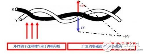
Use twisted pair cable to increase the degree of twisted pair and shield grounding
The electric field induces a common mode voltage in the cable, and the magnetic field can induce both the common mode voltage and the differential mode voltage in the cable. The induced interference of the electromagnetic field can be minimized by shielding, and the differential mode voltage induced by the magnetic field is further suppressed by using the twisted pair. The two wires of the twisted pair have a small loop area, and the current induced on each of the two adjacent loops of the twisted pair has opposite directions, canceling each other out. The denser the twisted pair of twisted pairs, the more obvious the effect is. It is recommended to twist 33 turns per meter. At the same time, in order to reduce the crosstalk of the CAN bus, the twisted pair should be shielded. In order to reduce the electrostatic discharge interference, the entire shield needs to be connected to the ground single point.
Increase impedance suppression common mode interference
In terms of common mode interference, differential transmission in accordance with ISO11898-2 has provided excellent protection. Within the common mode range supported by CAN transceivers, since the receiver only calculates the voltage difference between the buses, it filters out Common mode interference signal. High-energy, inductive, inductive interference signals can cause interfering signals that exceed the common-mode range of the transceiver. To suppress such interfering signals, a choke coil can be inserted in the input circuit of the CAN node, as shown:
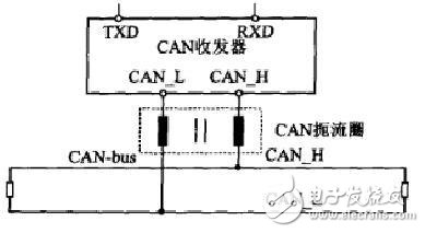
Inductive induced common mode interference is suppressed by a choke coil
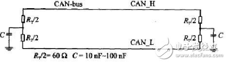
Separate bus terminal
In terms of high frequency, the electromagnetic compatibility of the CAN network can be improved by separating the bus termination resistors. At this time, the termination resistor is divided into two identical large resistors, and a coupling capacitor is grounded between the two resistors, as shown in the figure. Shorting the high frequency signal to ground without impairing the DC characteristics must ensure that the capacitor is connected to a fixed level ground.
Conduction protection - isolation and protection of conducted interference
Conducted interference mainly occurs in transient and transient processes, such as transient surges caused by the opening and closing of high-power switches, lightning strikes, etc., which are generally transmitted through CAN bus cables, which brings greater electromagnetic hazard. In the propagation path, these transient pulses and surges should be eliminated, so that CAN bus communication can be reliably performed.
TVS Diode TVS
The transient suppression diode is connected in parallel between the signal line and the signal ground to protect the cable from high voltage surges caused by lightning or electrostatic discharge. When the voltage on the TVS exceeds a certain amplitude, the device is turned on quickly, thereby discharging the surge energy and limiting the magnitude of the voltage within a certain range. It is recommended that two TVS tubes be used for two-way protection on each signal line of CANH and CANL.
Isolated transceiver
Isolation is the ideal method to solve the problem of conducted interference. It has good electrical insulation and anti-interference ability. Selecting the isolated transceiver first considers the transmission delay. For example, the optocoupler isolation delay is up to 25ns or more, and the magnetic coupling isolation is only 3~5ns. The delay time will affect the transmission distance and quality of the bus. It is recommended to use magnetic isolation. CTM1051 design interface transceiver circuit.

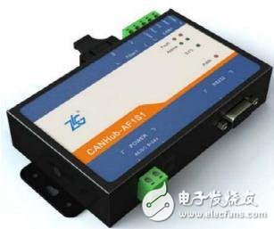
Optical fiber transmission
Adopt fiber transmission, such as the CANHUB-AF1S1 of Zhiyuan Electronics, to safely isolate interference.
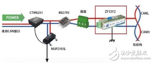
Signal protector
An external dedicated signal protector eliminates interference, such as ZF-12Y2 consumption interference intensity and CANbridge bridge isolation.
Third, summary
As one of the earliest manufacturers to introduce CAN technology in China, Zhiyuan Electronics has rich experience in the development and testing of CAN bus. It develops a comprehensive CAN bus analyzer - CANScope, which integrates mass storage oscilloscope and network analyzer. , bit error rate analyzer, protocol analyzer and reliability test tools, and organic integration and correlation of various instruments; redefining CAN bus development test methods, can be correct, reliable and reasonable for CAN network communication Sexual multi-angle evaluation; help users quickly locate faulty nodes and solve various problems of CAN bus application, is the ultimate tool for CAN bus development and testing.
KNM1L Series Moulded Case Circuit Breaker
KNM1L series Moulded Case Circuit Breaker is MCCB , How to select good Molded Case Circuit Breaker suppliers? Korlen electric is your first choice. All moulded Case Circuit Breakers pass the CE.CB.SEMKO.SIRIM etc. Certificates.
Moulded Case Circuit Breaker /MCCB can be used to distribute electric power and protect power equipment against overload and short-current, and can change the circuit and start motor infrequently. The application of Moulded Case Circuit Breaker /MCCB is industrial.
Korlen electric also provide Miniature Circuit Breaker /MCB. Residual Current Circuit Breaker /RCCB. RCBO. Led light and so on .
KNM1L series Molded Case Circuit Breaker,KNM1L series Small Size Molded Case Circuit Breaker,KNM1L series Electrical Molded Case Circuit Breaker,KNM1L series Automatic Molded Case Circuit Breaker
Wenzhou Korlen Electric Appliances Co., Ltd. , https://www.korlen-electric.com