
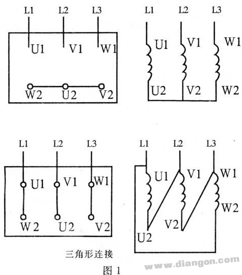
To repair or rewind the six lead wires of the three-phase winding of the three-phase asynchronous motor, the head and tail must be separated, otherwise the wiring in the junction box cannot be correctly wired. The head and tail of the six lead wires are marked with U1, V1, W1, U2, V2, and W2 respectively (the old numbers are D1, D4, D2, D5, D3, D6). Wherein U1 and U2 represent the head and tail ends of the first phase winding; V1 and V2 represent the head and tail ends of the second phase winding; and W1 and W2 represent the head and tail ends of the third phase winding. Different letters indicate different phases, and the same numbers indicate the same as the head or tail. When repairing the motor, if the six leads are complete, only the terminal block in the junction box is damaged. Replace the terminal block according to the connection method specified on the motor nameplate. The motor wiring method is divided into two connection methods: star (Y) and triangle (â–³). As shown in Figure 1. If the markings on the six leads have been broken or re-wound around the motor windings, the head and tail ends of the six leads must be identified and then connected to the terminal block as specified.
The method for determining the winding head and tail is as follows:
1. Determine the two wire ends of each phase winding with a multimeter resistance profile measurement. When the resistance value is approximately zero, the two test leads are connected to the two ends of a group of windings, and the two ends of the three windings are sequentially distinguished.
2. Multimeter method l.
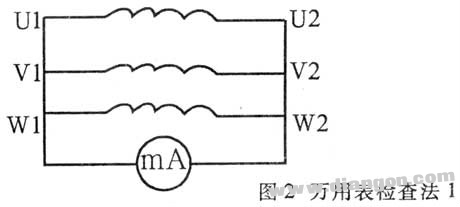
1 million use the table to set the mA file, according to Figure 2 wiring. Suppose one end is wired to the head (U1, Vl, W1) and the other end is the tail (U2, V2, W2).
2 Rotate the rotor by hand, such as the multimeter pointer does not move, indicating that the assumption is correct. If the multimeter pointer swings, it indicates that the assumption is wrong. It should be re-tested after adjusting the winding head and tail end of one phase, until the multimeter does not swing, the three line heads connected together can be determined as the head or the tail.
3. Multimeter method 2.
1 million meters set mA file, according to Figure 3 wiring.
2 Close the switch S, and if the multimeter swings to the right, the terminal of the battery positive electrode and the head of the multimeter negative test pen are the same as the head or the tail. If the pointer is reversed to the left, the terminal of the battery positive terminal and the terminal of the multimeter's positive meter are the same as the head or the tail.
3 Repeat the above test by changing the battery (or multimeter) to the two wire ends of the third phase winding to determine the head and tail of the third phase winding to determine the respective head and tail of the three phase winding.
4. Light bulb inspection method 1.
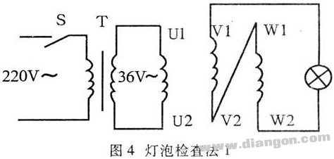
1 Prepare a 220/36V step-down transformer and connect it according to Figure 4 (small-capacity motor can be directly connected to 220V AC power).

2 Close the switch S. If the bulb is on, it indicates that the two-phase winding is the head and the tail are connected in series. The voltage used on the bulb is the vector sum of the induced electromotive force of the two-phase winding. If the bulb is not lit, it indicates that the two sets of windings are tail, tail or head, and the head is connected in series. The voltage applied to the bulb is the vector difference of the induced electromotive force of the two-phase winding.
3 Mark the determined wire ends and mark one of them with the 36V power supply to determine all the heads and tails of the three-phase winding.
5. Light bulb inspection method 2.
1 Wire as shown in Figure 5.
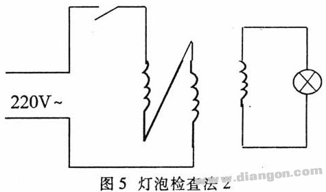
2 Close the switch S, if the 36V bulb is on, it means that the two-phase winding of the 220V power supply is connected in series with the head and tail. If the bulb is not lit, the two-phase winding is connected in series with the head, the head or the tail, and the tail.
3 Mark the determined wire head and mark one of the phases with the light bulb to determine all the heads and tails of the three-phase winding.
Thick Film Chip Resistors Chip resistors, Chip from Fixed Resistor directly translated, commonly known as SMD Resistor (SMD Resistor), is one of the metallic glass uranium Resistor.It is a resistor made by mixing metal powder and glass uranium powder and using screen printing method to print on the substrate.Moisture and high temperature resistance, low temperature coefficient.It can save the circuit space cost and make the design more refined.

Thick Film Chip Resistors,Smd Thick Film Chip Resistor,Thick Film High Voltage Chip Resistor,Chip Resistors Thick Film Resistors
YANGZHOU POSITIONING TECH CO., LTD. , https://www.pst-thyristor.com