1 Introduction
With the development of control technology, the function of the frequency converter is not limited to the speed control mode, and its torque control mode function has also been developed and applied. In particular, the mechanical properties of the transmission system and the transmission material that cannot install the tension detection element are very hard. In the case of speed control mode, it is difficult to meet the synchronous drive. The torque control function of the inverter is very convenient for synchronous drive. In our torque control mode, it is generally thought that the torque control is for a drive of a drive. Taiwan motor is more ideal, and a drive to drive multiple motors to do torque control is a fresh way. Here we use the open-loop torque of Danfoss FC302 inverter for traction and unwinding applications on the Guangzhou Huadu Lijun aluminum-plastic pipe production line.
2ã€Transmission technology introduction
The aluminum-plastic tube production line is mainly used to unwind, form, encapsulate (extruder), draw tube, and take up (or cut) the aluminum tape. The traction of the aluminum strip unwinding and forming pipe is realized by the open-loop torque of Danfoss FC302 inverter. It is well known that the movement state of the transmission system satisfies the equation of motion of the system: TM-TL=(GD2/375)*(dn/ Dt), where: TM is the electromagnetic torque of the motor, TL is the load torque of the production machine, including the torque of the motor shaft and the mechanical system connected to the shaft, the counter-torque formed by the tube tension, GD2 is rotating Part of the moment of inertia.
From the above equation, it can be seen that if TM-TL>0, the system is in an accelerated state; if TM-TL<0, the system is in a deceleration state; TM-TL=0, the system is in a stationary or constant state. Transmission structure schematic block diagram
3, the application of open-loop torque control inverter
Danfoss frequency converter FC302 inverter open loop torque control, can do the torque size can be adjusted, and the speed of the motor can use the external terminal analog 0-10VDC limit, so that will not cause the phenomenon of no-load speed, the following brief introduction The following torque control was successfully applied to traction and unwinding.
1) Unwinding part
When the aluminum tape is unwound, its tension requirement is not very strict and the precision is not very high. The aluminum hammer is pressed by the pendulum, and an angle sensor is used to detect the angle of the pendulum. The output signal of the angle sensor is 0. -5VDC. The speed control of the unwinding is controlled by the output of the angle control itself. The control principle of the inverter is as follows:
Function and parameter description:
A. Terminal 53 accepts the angle sensor 0-10 VDC signal as a speed limit.
Terminal 54 is a potentiometer 0-10VDC signal, as a torque adjustment
B. Important parameter settings
P1-00——————Configuration Mode: [4] Torque Open-loop Control
P1-01——————The motor control principle: [1]VCC
P3-15————-Reference value source: [2] Terminal 54
P3-10[0]—Preset reference 0: Set according to requirements: -XX% (negative reverse direction)
P4-10——————Motor Direction: [2] Bidirectional
P4-21————- Speed ​​Limit Factor Source: [6] Terminal 53
P6-10————- Terminal 53 Low Voltage: Actual Value Measured from the Lowest Point of the On-Site Pendulum
P6-11————- Terminal 53 High Voltage: Actual value measured from the highest point of the on-site pendulum
2) Traction section: The traction is carried by the upper and lower two motors that drive the belt together to send the pipe. One inverter drives the two motors. The inverter adopts the open-loop torque control mode. The device can not use the parameters to automatically identify the motor, you must manually set the advanced motor parameters, P1-30, P1-31, P1-33, P1-34, P1-35, P1-36, the adjustment method is: first up and down In the middle of the pinch belt, run the inverter and select the proper torque value. Pull the tube firmly to make the two clamps stop. When the tube is relaxed, the clamp belt runs. The advanced motor parameters under this condition are OK. Its parameters are almost the same as unwinding, and the control principle is as follows:
4, summary
This system is relatively simple as a method of tension control. It is not a complete constant tension control. However, due to the fast response speed of Danfoss frequency converter, and the system's tubes and aluminum belt can withstand a certain tension changes, this type of The method is to fully meet the process requirements, and relatively improve the system performance, and has a certain degree of economical, practical, practically proven to be feasible.
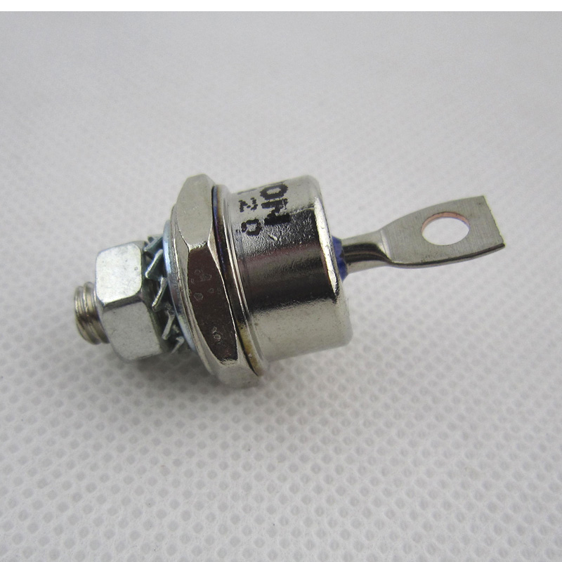
Fast Recovery Diode (FRD) is a semiconductor diode with good switching characteristics and short reverse recovery time. It is mainly used in switching power supplies, PWM pulse width modulators, inverters and other electronic circuits as high-frequency rectifier diodes. Free-wheeling or damper diodes are used. The internal structure of the fast recovery diode is different from that of an ordinary PN junction diode. It belongs to a PIN junction diode, that is, a base region I is added between the P-type silicon material and the N-type silicon material to form a PIN silicon wafer. Since the base area is thin and the reverse recovery charge is small, the fast recovery diode has a short reverse recovery time, a low forward voltage drop, and a high reverse breakdown voltage (withstanding voltage).

Fast Recovery Stud Diode,Stud Type Fast Recovery Diode,Fast Recovery Diode,Stud Rectifier Power Diode
YANGZHOU POSITIONING TECH CO., LTD. , https://www.yzpst.com
