
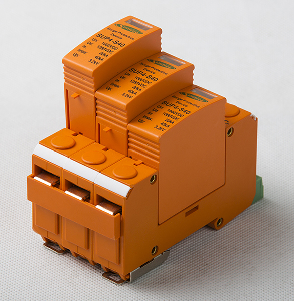

The SUP series Surge Protection are designed to protect against lightning surge voltages in photovoltaic power supply networks.
These units must be installed in parallel on the DC networks to be protected and provide common and differential modes protection. The SUP series is available for the main operating voltages in photovoltaic: 1000 Vdc.
The use of SUP series Surge Protection is recommended at both ends of the DC power supply line (solar panel side and inverter/converter side),
Especially if the line routing is external and long. The electrical diagram of the SUP series is based on high energy PV equipped with specific thermal disconnectors and related failure indicators.
The SUP series is made with plug-in modules to allow a fast and easy maintenance in case of failure (disconnection from the DC network).
Â
| SUP2-PV series surge protector | SUP4-PV | ||
| PV DC specific (LEC 6614-1/EN 61643-11) | |||
| Pole | 2 pole | 3 pole | |
| Electrical Parameter | |||
| Classifical test | II | II | |
| Uoc max (V DC) | 500 | 900 | |
| Uc (V DC) | 500 | 1000 | |
| In(8/20)us (KA) | 20 | 20 | |
| Imax(8/20)us (KA) | 40 | 40 | |
| Up (KV) | 2.0 | 3.8 | |
| Remote control and indication | |||
| Indication window | |||
| Plug-in module | |||
| Remote signal contact | |||
| Remote signal contact | Max working volt | 250V AC/30V DC | 250V AC/30V DC |
| Max working amp 1A (250V/AC) | 1A (250V/AC) | 1A (250V/AC) | |
| 1A (30V DC) | 1A (30V DC) | 1A (30V DC) | |
| Wiring & installation | |||
| Wiring capacity(mm2) | Hard wire | 4-25 | 4-25 |
|
 |
Flexible wire | 4-16 | 4-16 |
| Stripping length | 10 | 10 | |
| Terminal screwa | M5 | M5 | |
| Torque(Nm) | Main ciruit | 3.5 | 3.5 |
| Remote signal contact | 0.25 | 0.25 | |
| Protection class | All profile | IP40 | IP40 |
| Connection port | IP20 | IP20 | |
| Installation environment | No obvious shock and vibration | ||
| Altitude(m) | ≤ 2000 | ≤ 2000 | |
| Working temperature | -3.0--+70 | -3.0--+70 | |
| Relative humidity | 30%-90% | 30%-90% | |
| How to install | Install with H35-7.5/DIN35 stell mounting rail | ||
| Size(mm) (W*H*L) | W | 36 | 54 |
| H | 90 | 90 | |
| L | 67.6 | 67.6 | |
| Weight (KG) | 0.25 | 0.38 | |
| Nominal PV system volt | 600V | 100V | 1200V |
| MCOV(UCPV) | 700V DC | 1170V DC | 1200V DC |
| Max system discharge Current (8/20us) (Imax) | 40KA | 40KA | 30KA |
| Volt protection leve (UP) | ≤ 2.5KV | ≤ 4.0KV | ≤ 4.5KV |
| Volt protection Level at 5KA (UP) | ≤ 2.0KV | ≤ 3.5KV | ≤ 4.0KV |
| Integrate fuse breaking capacity/interrupting rating | 30KA/1000V DC | 30KA/1000V DC | 30KA/1200V DC |
| Technology | Short-circuit interruption (SCI) overcurrent protection | ||
| Operating temperature range | -40 to +80 | ||
| Nominal discharge current | 12.5KA | ||
| Response time (ta) | <25ns | ||
| Operating state/fault indication | Green (good) / Red (replace) | ||
| Mounting | 35mm DIN Rail per EN 60715 | ||
| Degree protection | IP20 | ||
| capacity | 3 modules DIN 43880 | ||
AC SPD
| AC SPD | Class C | ||||
| Max. continuous voltage Uc | 275 V | 320 V | 420 V/ 440V | ||
| pole | 1P 2P 1P+N 3P 3P+N 4P | ||||
| Nominal discharge current (8/20μs) In | 20 kA | ||||
| Max. discharge current (8/20μs) Imax | 40 kA | ||||
| Lightning impulse current (10/350) [N-PE] limp | ≤ 12.5 kA | ||||
| Voltage protection level [L-N] Up | 1.0 kV | 1.5kV | 1.6kV | ||
| Voltage protection level [N-PE] Up | ≤ 1.2kV | ||||
| Response time tA | ≤ 25 ns | ||||
| Max. back-up fuse | 125 A gl/gG | ||||
| Short-circuit withstand current | 25kA/50Hz | ||||
| Operating temperature range TU | -40°C+80°C | ||||
| Cross-sectional area (min.) | 1.5 mm2 solid / flexible | ||||
| Cross-sectional area (max.) | 35 mm2 stranded / 25 mm2 flexible | ||||
| Mounting on | 35 mm DIN rail acc. To EN 60715 | ||||
| Degree of protection | IP 20 | ||||
| Housing material | Thermoplastic; extinguishing degree UL 94 V-0 | ||||
| Remote signaling contact (floating switch) | Yes (optional accessory) | ||||
| Switch capacity | AC: 250V/0.5A; 125V/3 A | ||||
| Cross-sectional area for remote signaling terminals | Max. 1.5 mm2 solid / flexible | ||||
| Product Model | Product Model | SUP1 D,C,B | |||||||||||||||
| The number of poles | 1P , 2P , 1P+N, 3P , 3P+N, 4P | ||||||||||||||||
| Rated working voltage Un(V) | 230/400 | ||||||||||||||||
| nominal discharge current (8/20μs)kA | 10 | 20 | 30 | 60 | |||||||||||||
| Max discharge current | 20 | 40 | 60 | 100 | |||||||||||||
| Max Continuous Operating Voltage | 275 | 320 | 440 | 460 | 275 | 320 | 420 | 460 | 275 | 320 | 420 | 460 | 275 | 320 | 420 | 460 | |
| Protection level | <1.0 | <1.4 | <1.6 | <1.8 | <1.2 | <1.6 | <1.8 | <2.0 | <1.5 | <1.8 | <2.0 | <2.2 | <1.6 | <1.8 | <2.2 | <2.4 | |
| Prepose fuse | 25AGL | 50AGL | 80AGL | 80AGL | |||||||||||||
| Response time (ns) | <25 | ||||||||||||||||
| Leak current 75% Uc 1mA | <20μA | ||||||||||||||||
| Testing classification | II | ||||||||||||||||
| Protection class | IP20 | ||||||||||||||||
| Ambient temperature limited | -40°C~+80°C | ||||||||||||||||
| Material of insulation sheath | PBT/PA66 | ||||||||||||||||
| Fire Retardant level UL94 | VO | ||||||||||||||||
| Installation method | 35mm standard electric rail | ||||||||||||||||
| Outside color | red | ||||||||||||||||
| Recommended fuse or breaker A | 40~63 | ||||||||||||||||
| Sectional area of the linked power line (mm ) |
Phase/Null line | 1.5~3.5 hard wire | |||||||||||||||
| Ground lead | 1.5~3.5 double color | ||||||||||||||||
| Accord to standards | IEC61643-1 IEC61643-21 UL1449 | ||||||||||||||||
FAQ:
Q:Â What's your warranty ?
A: Two years
Q:Â How can i trust you and your company ?
A: Suntree is a group company, we have 6 subcompanies.
Have cooperation with LS, EKF the world-class companies.
Our company over 500 employees, products pass
CE,IEC,TUV,SAA, RCM, ROHS certificates.
Q: What's your contact information:
A: Our address: Liushi town, Zhejiang province, China.
Q: What's your shipment method?
A: We ship by Express, by air, by sea, by train. Normally we checked and compare,
then provide customer the most proper shipment method.
Q: What's about MOQ?
A: First order MOQ=1pcs
Q: If i want to release order, what's the payment method you accept ?
A: We accept T/T, Paypal, Western union, L/C.
Q: If i want to release order, what's the process?
A: Thanks. You can send inquiry to us by made-in-china,
or send us by email, we will reply within 24hrs.
Thank you & Now pls send your inquiry ! ^!^
What is 2.4g wireless module?
2.4g line module operating frequency in the range of 24400-2484mhz, can communicate through the scanning protocol, air rate up to 1Mbps, output power up to +4dBm, the module has the advantages of low power consumption, cost-effective. Movingcomm's current 2.4g antenna modules are: IOT04, IOT05, IOT09, IOT18, IOT60, etc. Users can choose a variety of modules with a transmission distance of 50-500 meters according to cost considerations.
Second, the role of 2.4g wireless module
Function 1, for the formation of a star topology wireless communication network, and must be a multi-point star topology, some extraordinary places need wireless communication. On the one hand, the transmitting and receiving module is cheap, and the cost of forming the star topology is relatively low. On the other hand, the transmitting and receiving module can adopt the modular design, which is small in size, easy to use and easy to integrate. For the wireless network with low communication speed and close distance, the transmitting and receiving module is very practical.
Function 2, for wireless multi-channel (parallel) control. Such as complex remote-controlled robots, some places require multi-channel (parallel) control. One method is to use the receiving module to directly connect to the decoder, and then connect to the relays and other electronic components to drive the subsequent controlled object; the other method is to use the receiving module to connect to the single chip microcomputer, and after the data is disposed of, the single chip microcomputer is connected to the relays and other electronic components to drive the subsequent controlled object. Usually a pair of transmitting and receiving modules can achieve up to six parallel wireless control, if the required number of channels is greater than six, you can use multiple pairs of transmitting and receiving modules, and work at the same time to meet the actual needs.
Function 3, used for general serial port, RS232 antenna data transmission, there are usually many control instruments and equipment using serial port, and communication with these devices must meet the requirements of serial port. In some extraordinary places, when the industrial control site must use the antenna transmission mode, it is natural to choose the transmitting and receiving modules mentioned in this article, but it must be explained here that to use this communication mode, the corresponding software must be prepared at the transmitting end and the receiving end respectively to achieve the conversion of file formats, in order to achieve the purpose of wireless communication, if the communication system is full-duplex. It can be achieved by using two pairs of transmitting and receiving modules, working simultaneously.
Third, 2.4g wireless module application field
2.4G wireless module is widely used in wireless health sports products, wireless mouse and keyboard, product information push, wireless remote sensing, wireless ranging system, alarm security system, smart home, toy control, tire pressure monitoring and other fields. With the 2.4G wireless module, all the whole house wireless smart home can be linked together, you can control all the smart home devices through the link of the network, and then you can control the switch of all the whole house wireless home, adjust the brightness of the lamp, adjust the rise and fall of the curtain, etc., through the continuous innovation of technology, The whole house wireless smart home can be controlled by a small white robot voice, can be controlled by a smart scene panel, can be controlled by sensors and so on.
Four, 2.4g wireless module how to choose antenna
In general, the 2.4g wireless module requires an impedance of 50 ohms, a red wire used with 2.4g, a 2.4g folded rod antenna, a 2.4g gold-plated straight head rod antenna, a 2.4g gold-plated elbow rod antenna, and a 2.4g small suction cup antenna. These antennas are special antennas designed for 2.4g wireless communication system, antenna standing wave ratio performance is good, small size, clever structure, easy installation, stable performance, with good anti-vibration and aging ability.
2.4G Router Module,M2 Wifi Module,2.4 Ghz Wifi Module,Mini Wifi Module
Shenzhen MovingComm Technology Co., Ltd. , https://www.movingcommiot.com