
Are you still worried that your keyboard is "fear of water"? The piezoelectric disc keyboard solves your worries. The keyboard uses a piezoelectric disc as a sensor and buzzer to detect slight pressure on a 0.4mm thick stainless steel plate, which is both waterproof and vandal resistant. Here we will introduce you to the design of the piezoelectric wafer keyboard.
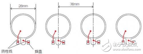
The core part of the sensor is a piezoelectric disc, which is usually used as a buzzer. Here, Murata's 7BB-35-3 is used. Its outer diameter is 35mm, and the sensing area has a diameter of about 20mm. On the PCB, the PCB contains electronic components and has round holes to allow the ceramic material to move freely. In this example, a 3mm thick self-adhesive foam rubber is used to fix the wafer to the PCB. The assembly is clamped to the back of the front panel with reasonable pressure.
PCB layout and opening
Touching the outer panel with your fingers, the steel (or other material) will be slightly deformed, and a small increase in pressure will be transmitted to the piezoelectric disc through the rubber. This pressure is sufficient to generate a voltage that can be detected by the microprocessor. At this point, the processor will use all the discs as a buzzer and will respond with a beep.
Four buttons are used in this design example. The microcontroller used is the uPD78F0513 from Renesas Technology (formerly NEC). Of course, other microcontrollers can also be used.
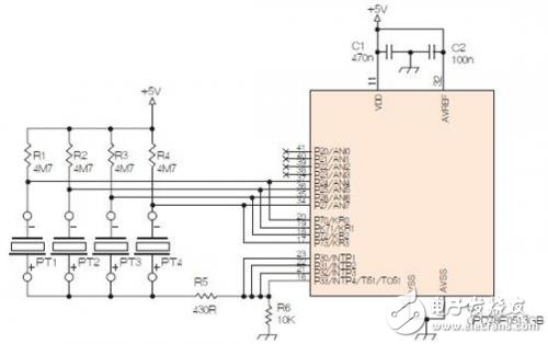
The smaller electrode of the piezoelectric wafer is connected to the ADC input of the microcontroller and connected to the positive supply via a large resistor. In addition, it is connected to other port inputs (P7) that are initially in a high impedance state. The other electrodes (larger electrodes) of the piezoelectric wafer are connected together to several parallel port bits (P3) to obtain a low impedance value. This step is not necessary if the port is missing and has sufficient output current. These ports will initially be low. Pressing the wafer with your finger to a slight deformation reduces the voltage supplied to the input of the ADC.
Piezo keyboard/buzzer schematic
At startup, P3 is low and P7 is high. The piezoelectric wafer is quickly charged. The capacitance of the piezoelectric wafer is about 30nF. After a few microseconds, P7 is set to a high impedance input.
The program continuously scans the ADC input. Due to the large capacitance of the wafer, the voltage changes very slowly and no fast scanning is required. It is set to perform voltage measurement every 1 ms in a specific application, so each wafer is inspected every 4 ms.
When the input voltage is reduced below the preset voltage by the button depression, the controller processes the input and then uses all parallel wafers as buzzer. When using a 0.4mm thick steel plate, a threshold of 1.5V below the 5V power supply is sufficient to obtain good sensitivity; if a thicker front plate is used, there is still a large margin to increase the sensitivity.
To beep, set P7 to a low impedance output and P3 to the opposite polarity, which will output a square wave at the resonant frequency of the piezo (in this case 2800 Hz). The buzzer lasts for 250ms and the drive current is limited by R5. After the beep is over, P3 returns to 0, and P7 is briefly set to 5V again to charge the wafer.
Ac Magnetic Contactor,Ac Electrical Contactor,Ac Series Contactor,Ac Contactor For Switching Capacitor
NanJing QUANNING electric Co.,Ltd , https://www.quanningtrading.com