
When performing microwave component testing, the network analyzer must first be calibrated. There are two options for calibration: (1) Calibration with an electronic calibration component. The advantage of this calibration method is that it is convenient, fast, and programmable. However, the disadvantage is that the calibration result is not very accurate and the accuracy of the test results. The impact is large; (2) manual calibration is used. The advantage of this calibration method is that the calibration result is high in accuracy and reliability, and the disadvantage is that it takes more time. Considering that the microwave components to be inspected are important devices in key parts of a key model, manual calibration is currently used. After the calibration is completed, the tested microwave components are connected to the network analyzer through the matched connectors, and an automatic test program is run on the computer to record and analyze various performance indexes of the microwave components, and automatically determine whether the microwave components are qualified. product.
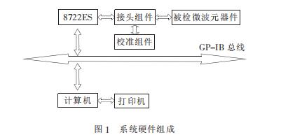
2, the hardware components of the microwave component inspection automatic test systemThe automatic test system is mainly composed of a test instrument, a computer, a GPIB card connecting the instrument and the host computer, and a printer. The test instruments mainly refer to the vector network analyzer, namely the 8722ES, the network analyzer calibration component and the network analyzer connector assembly. The hardware of the microwave component inspection automatic test system is connected through the GP-IB bus, as shown in Figure 1.
When performing microwave component testing, the network analyzer must first be calibrated. There are two options for calibration: (1) Calibration with an electronic calibration component. The advantage of this calibration method is that it is convenient, fast, and programmable. However, the disadvantage is that the calibration result is not very accurate and the accuracy of the test results. The impact is large; (2) manual calibration is used. The advantage of this calibration method is that the calibration result is high in accuracy and reliability, and the disadvantage is that it takes more time. Considering that the microwave components to be inspected are important devices in key parts of a key model, manual calibration is currently used. After the calibration is completed, the tested microwave components are connected to the network analyzer through the matched connectors, and an automatic test program is run on the computer to record and analyze various performance indexes of the microwave components, and automatically determine whether the microwave components are qualified. product.
3, microwave component inspection automatic test system software design 3.1 test program programming language selectionThere are currently two major classes of programming languages ​​for instrumentation. One is graphical programming software represented by NI (National Instruments) LabVIEW and Agilent's VEE. LabVIEW is a general-purpose software, and HPVEE (Visual Engineering Environment) is an engineering visual programming language specially developed for HP equipment. This type of graphical software has two notable features. First of all, it completely graphically handles the entire language, providing a modular programming tool that can be generated by simply connecting the icons with the mouse. The graphical software also provides data flow display and program flow display, making the debugging of the program very intuitive and visual. Secondly, the graphical software provides an intuitive soft panel (InstrumentPanel) and flexible direct input/output (DirectI/O) mode for instrument control. The former can use the mouse to operate the instrument panel; the latter can read and write the instrument in any data format, and can directly write control interfaces (such as GP-IB and GPIO) with the underlying commands. Using graphical software can save 30% to 80% of the time compared to using other languages, but the source program is poorly readable, inefficient, has little scalability and scalability, and is weak.
Another type of software is text programming software represented by NI (National Instruments) LabWindows and Agilent's HPBasicforWindows. One of its greatest advantages is that it is easily integrated with other programming software (ANSIC, Visual C++, Visual Basic). To achieve performance verification, functional testing, calibration, and data acquisition and control.
Consider the complex test function that the automated test program needs to read the data and generate reports. Therefore, the program is developed by Microsoft Visual Basic and uses third-party controls (mainly NI's ComponentWorks, LabView, Agilent's VEE, etc.).
3.2 Design requirements for test proceduresThe test program in the automatic test system should improve the test efficiency under the premise of correctly completing the test task, so the test program should meet the following requirements:
(1) Realizing the connection between the test instrument and the computer;
(2) setting up the test instrument;
(3) reading test data;
(4) processing test data;
(5) Generate a report.
Microwave oven component testing method
First, the magnetron detection method:
1. Test between the magnetron filament terminals, the resistance value should be less than 1Ω;
2. In any filament terminal and magnetron (grounded, tested, the resistance value should be infinite; if the resistance is small or zero, then the magnetron should be replaced.
Second, high voltage transformer detection method: detecting three windings:
1, the primary winding, about 1.45Ω
2, the secondary winding, about 112Ω
3, filament winding, less than 1Ω
If the measured reading does not meet the above data, the high voltage transformer may be faulty and should be replaced.
The design idea of ​​the test program is written in Microsoft's VB language. The communication interface uses NI (National Instruments)'s USB-GPIB interface and its supporting IEEE488.2 for Windows driver software. After adding the interface driver software to the VB development environment, you can use the vector network analyzer's control code to control the instrument. After controlling the instrument, the SCPI instruction is used to set the instrument to the corresponding test state. When the device under test is connected, the test is started. After the test is completed, the test data is read and saved to the database, and the test is generated after all the tests are completed. Report and finally exit the program and release the controlled instrument.
3.3 Test program design 3.3.1 Test program compositionThe entire test program strictly follows the top-down (Down-Down) and modular design ideas, so that each functional module has good introversion. The mutual communication between the modules is uniformly scheduled by the main program, so that the structure of the program is clear and easy to understand, the maintainability is greatly enhanced, and the management and upgrade in the future are relatively easy. The test program structure is shown in Figure 2. The test program consists of two major parts. The first is the main form of the program. After running the test program, the form is first entered. The second is the test module corresponding to all kinds of microwave components. After entering the main form, there are 7 command buttons on the main form, corresponding to the test modules that enter different microwave components. The seven test modules are: 1) seeker main channel cable assembly test; (2) seeker correction channel cable assembly test; (3) fuze pair cable assembly test; (4) fuze semi-rigid cable assembly test; (5) turn waveguide test; 6) Circulator test; (7) Load test.
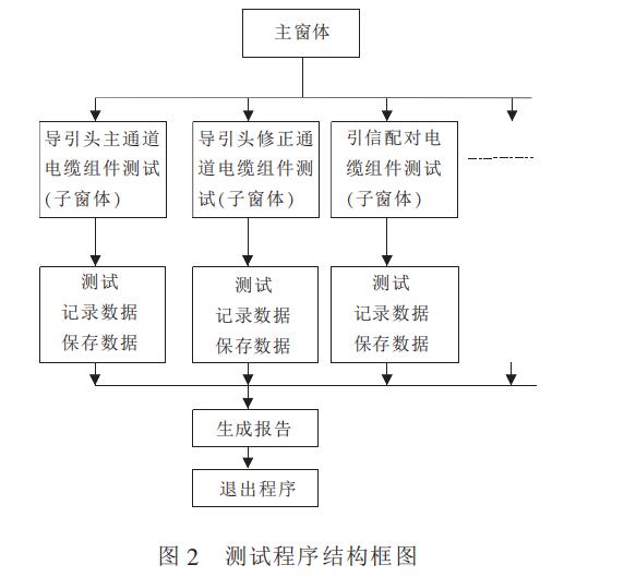
The test program realizes the test by controlling the test equipment, and collects the required data at the same time, and the data is saved in the database, and compared with the performance indexes of the corresponding microwave components that have been set in the program, and the check is obtained. Whether the components are qualified products. After all the tests are completed, click Generate Report and the program will transfer all the data from the database to the test form and save it to the directory where the program is created. Here, the database functions as a data transfer save. When generating a report, different report templates are called according to the type of the test piece, and the number of pages of the report is automatically determined according to the number of the test pieces, and a report is generated.
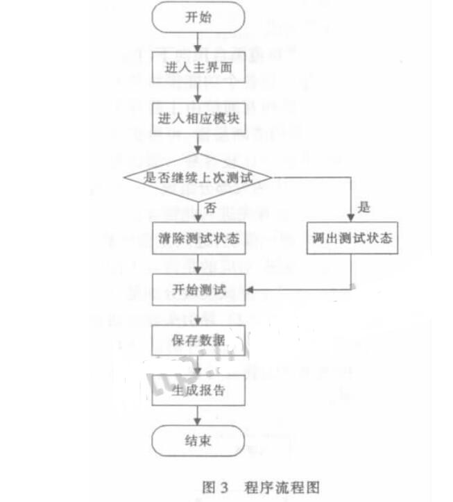
3.3.3 How to use the test programThe program flow chart is shown in Figure 3.
Take the test of the main channel cable component of the seeker as an example, analyze the application of the test program in actual work, and verify whether the test program meets the work requirements and meets the use requirements.
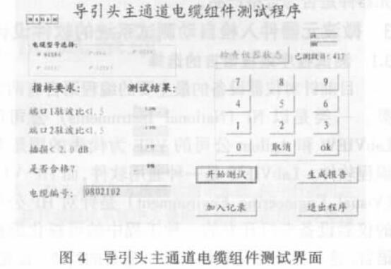
Figure 4 shows the test interface of the main channel cable assembly of the seeker. The test conditions of the batch cable assembly and the test results of the 0802102# cable assembly are clearly seen in Figure 4. The 0802102# cable is the 417th cable module of this type tested continuously. The port 1 VSWR is 1.249, the port 2 VSWR is 1.174, and the cable insertion loss is 1.77dB. According to the cable assembly specifications. The technical indicators provided determine that the cable is a qualified product.
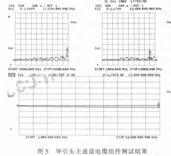
Figure 5 shows the test results of the seeker main channel cable assembly, which is the test result of the 0802102# cable assembly displayed on the 8722ES vector network analyzer. Through this interface, the technical status of the numbered cable assembly in the entire test frequency band is clearly seen, and it is clear at a glance whether it is a qualified product. This provides a more comprehensive and reliable basis for the test screening of cable assemblies.
Through the above illustration, the application of the automatic test system in actual work is clearly and accurately known, and the working mode of the automatic test system is understood. The test of the automatic test system is known through the comparison of Fig. 4 and Fig. 5. The data collected by the interface is true, accurate and reliable, and is exactly the same as the reading value of the test instrument, ie vector network analyzer. This proves that the automatic test system meets the actual work requirements and can be used in actual work.
5, the characteristics of the test programFirst, the test program is highly modular. Due to the modular programming, many common program segments are modularized and applied to different test modules. The structure of each test module is similar, but the operation is independent of each other and does not interfere with each other, making the program easy to maintain. It can also be easily extended. More importantly, the application is stable, and even if one module fails, it will not affect the application of other modules. Secondly, the last test status can be automatically memorized. The automatic test program has an automatic memory function, so that it is not necessary to generate a report every time the test is interrupted before exiting the program, and there is no need to make any settings before exiting the test program, which improves the simplification of the program. When you enter the automatic test system again, the system will prompt the user whether to continue the last test or re-run the new test, which is convenient and fast, and is very beneficial to the detection of a large amount of microwave components.
6, the conclusionAlthough the automation of the test process is realized in the process of detecting the microwave components, the work efficiency is greatly improved, and the accuracy and reliability of the test results are improved. However, during the test, the installation of the test port of the component to the vector network analyzer is still manual, and the consistency of each installation state is not guaranteed, which directly affects the accuracy of the test result. In addition, the interface of the microwave components that are inspected is not the same, there are SMA, waveguide, etc. At the same time, the ready-made test fixture can not be used in the test, so there is a certain difficulty in the selection of the fixture. Take the test cable assembly as an example. When using full manual test, it takes about 4 minutes to test a cable. Now the automatic test system is used. It takes about 2 minutes to test a cable. If the problem of the test fixture can be solved, the test result will not be greatly improved. The accuracy will further improve work efficiency.
Product Name: Custom Screen-Printing Silicone Rubber/Keypad Keyboard
Brand OEM
Certificate ISO9001
Experience More than 20 years' experience
Can provide customers with professional product design. We HAVE accumulated MANY years of experience in Japanese customers, the company has stable quality management experience in mass production orders, and can meet the customer's delivery time requirements and quality requirements on time. Now our products are widely used in communications, medical, electronics, digital, watches, automobiles and other high-end fields. With the ISO9001 factory certification, we have gradually become the industry leader with good management, leading technology, excellent quality, timely delivery and thoughtful service.
A factory specializing in the design and manufacturing of precision products, including SUS, plastic products, brass, aluminum, engineering plastics and precision casting, precision extrusion, stainless steel precision casting, as well as specialized metal surface treatment, mold design and mold manufacturing. Our factory has excellent designers and rich manufacturing experience, to provide customers with high quality products, reasonable prices and excellent service. We also continue to introduce foreign advanced precision equipment, with imported automatic lathes more than 30 sets, more than 70 sets of automatic CNC machine tools, screw machine, hardware punching machine and other automatic production chain.
Keypad,Keyboard,Button,Switch,Screen
KEDA MEMBRANE TECHNOLOGY CO., LTD , https://www.kedamembrane.com