At present, white LEDs are mainly used as backlights for mobile phone screens. Since the screen sizes and specifications provided by different suppliers are different, the backlight driving method is different from the backlight driving chip. However, there are two main types of backlight chips currently used, one is a boost chip that drives a series LED or OLED, and the other is a charge pump chip that drives a parallel LED.
For series LED backlights, the lithium battery voltage needs to be boosted to different voltages depending on the number of LEDs in series. For OLED backlights, it is generally required to boost the lithium battery to 12V. Both applications require a boost chip for backlighting. Sipex's SP6690 can drive up to eight LEDs in series (Figure 1a). At present, the efficiency of the boost driver chip is between 75% and 85%, and the brightness of the light is guaranteed to be uniform, but a storage inductor is required, which causes a certain electromagnetic interference problem.
For parallel LED backlight applications, Sipex's SP6683 charge pump can output up to 300mA of drive current to drive up to 10 parallel LEDs (Figure 1b). Sipex's charge pump driver IC is a constant current LED driver that operates in 1x mode and 1.5x mode, with a maximum efficiency of 92% in 1x mode and 60% to 70% in 1.5x mode. The charge pump works by charging and discharging the capacitor at a very high switching frequency to achieve power conversion. The buck and boost modes are automatically switched according to the input voltage, so it does not need an external inductor, but stores energy through a capacitor.
As LED technology continues to advance, the LED turn-on voltage drop is declining. Sipex's low-dropout linear LED driver SP761x series eliminates the need for boosting, so the peripheral circuitry is very simple, no inductors or capacitors are needed, and only one resistor is needed to set the current through the LED. The SP7611A and SP7612 application circuits shown in Figures 2a and 2b can drive 4 LEDs and 3 LEDs respectively, and the SP7614A can drive 2 LEDs.
Figure 1: (a) SP6690 backlight application circuit diagram; (b) SP6683 backlight application circuit diagram.
The following takes SP7611A as an example to introduce the application of the low-dropout linear LED driver chip SP761x series. Sipex's low-dropout linear LED driver chip is different from traditional LED driver chips. They do not need to boost the cell's polymer lithium battery voltage to illuminate the LED, but a buck-based constant current LED driver chip. As shown in Figure 2a, the SP7611A is a current-carrying LED driver chip. The current flowing through the LED is proportional to the current on the set resistor Rset, while the current flowing through the LED is also forward-passing the voltage drop Vf of the LED and the cathode of the LED. Voltage related. Therefore, an important condition for Sipex low-dropout linear LED driver applications is that the LED's turn-on voltage drop cannot be too high. LEDs with a turn-on voltage drop of 3.2V or less are generally recommended.
The biggest advantage of the SP761x series is that the application is simple, and the peripheral circuit requires only one resistor for setting the current. When the LED cathode to ground voltage VLED ≤ 300mV, the current flowing through the LED is:
ILED=200×(VCONTROL-VCTRL)/Rset
Figure 2: (a) SP7611A backlight application circuit diagram; (b) SP7612/12A backlight application circuit diagram; (c) Schematic diagram of adjusting backlight brightness through two GPIO ports and two resistors.
When the LED cathode to ground voltage VLED ≥ 500mV, the current flowing through the LED is:
ILED=435×(VCONTROL-VCTRL)/Rset
Among them, 200 and 435 are the magnification of the current. From this it can be seen that the LED current is equal to the current flowing through Rset multiplied by a magnification, and this amplification is related to the conduction voltage drop of the LED (as shown in Figure 3).
Figure 3: Graph of the amplification of the LED current versus the conduction voltage drop of the LED.
In mobile phone backlight applications where brightness needs to be adjusted, the SP761x family of LED drivers can adjust brightness in a number of ways:
1. Analog adjustment. As shown in FIG. 2a, the magnitude of the given voltage VCONTROL or the current setting resistor Rset can be adjusted to adjust the LED current for the purpose of controlling the brightness.
2. Digital adjustment. In the case where the voltage VCONTROL and the current setting resistor are given, the PWM signal can be input through the pin CTRL to adjust the brightness. The PWM signal can be output through the GPIO port of the mobile phone platform, and the duty ratio of the PWM is set by the software to achieve the purpose of controlling the brightness. The maximum frequency of this PWM signal can reach 1MHz, but considering the current LED response speed will not exceed 10kHz, the recommended frequency is 500Hz~1.5kHz.
Table 1: Settings table for GPIO ports.
3. Adjust the backlight brightness by dividing the two GPIO ports and two resistors into six levels, as shown in Figure 3c. The GPIO port can be set with reference to Table 1, where R1 is greater than R2, and the specific resistance can be set according to the actual application.
Efficiency is also an important parameter in mobile phone backlighting applications. The most accurate algorithm for backlight efficiency should be to divide the energy consumed on the LED by the input energy. Since the operating leakage current of the SP761x series low-dropout linear LED driver chip is very small (uA level), the output current flowing through all the LEDs can be approximately equal to the input current, and the overall efficiency is equal to the LED's turn-on voltage drop Vf and the input voltage (ie, the battery). The ratio of the voltage Vbattery).
Eff=100×Vf/Vbattery
It is recommended that the LED's turn-on voltage drop be less than or equal to 3.2V, and take Vf = 3.2V, the efficiency is shown in Table 2. When the battery voltage is less than 3.6V, the overall backlight efficiency is higher than 90%; when the battery voltage is 4.2V, the minimum efficiency is also 76%. At present, the working range of lithium batteries for mobile phones ranges from 3.4V to 4.2V.
About 20% of the battery energy is concentrated between 4.2 and 4.0V, 70% of the energy is concentrated between 4.0 and 3.5V, and the remaining 10% of the battery energy is concentrated in the range below 3.5V, so the battery voltage is from 4.0. The efficiency of the ~3.5V interval is the most important. The SP761x series has an efficiency of 80% to 91.4%, and the closer the battery voltage is to the LED's turn-on voltage drop, the higher the efficiency.
Compared to the boost driver chip and the charge pump chip, the low-dropout linear LED driver chip SP761x series is not inferior in efficiency and has better performance when the battery voltage is lowered. In the case of a reduced battery voltage, the backlight efficiency of the SP761x series is increased, while the backlight drive efficiency of the boost drive and charge pump drive chip will decrease. Although the current boost driver chip and charge pump driver chip can achieve more than 90% efficiency, the overall backlight efficiency is between 75% and 85%, and energy storage components such as inductors or capacitors are required.
The low-dropout linear LED driver SP761x series is a common-anode constant-current LED driver chip. It does not require energy storage components. The peripheral is simple. Only one current setting resistor is needed to adjust the backlight brightness by analog or digital. It has a maximum efficiency of more than 90%, and the overall backlight efficiency can reach about 85%. In addition, Sipex is driving this market for low dropout linear LED drivers and will continue to introduce a common cathode driver chip to enrich this product line.
Variable Frequency AC Power Supplies
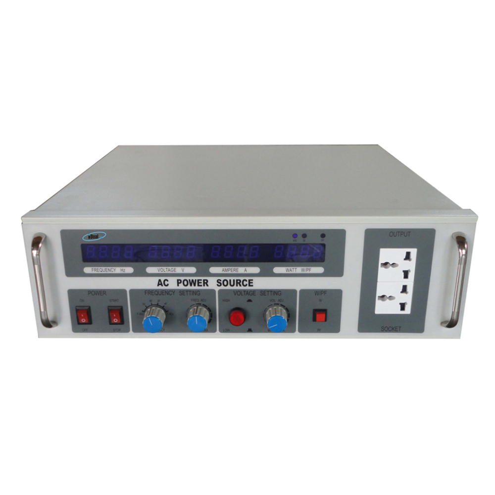
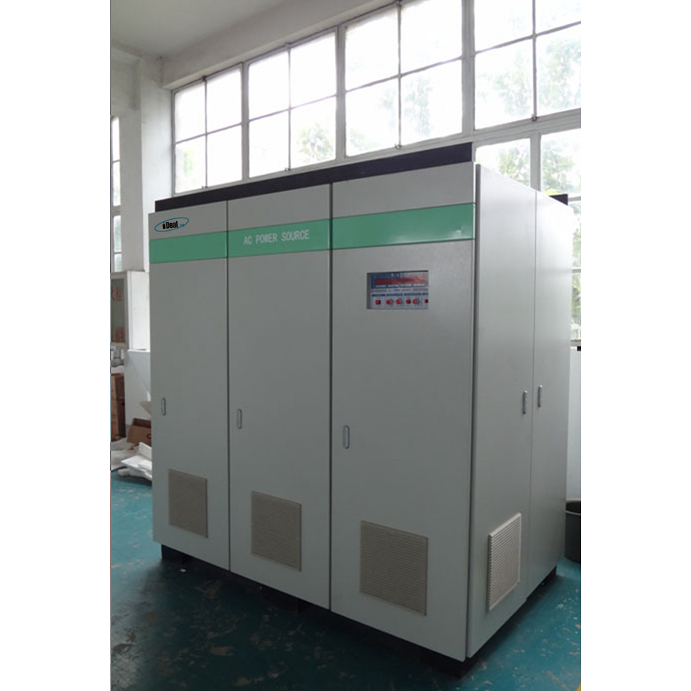
The VFP series AC Power Supplies are high precision, high efficiency, low THD adjustable AC power supplies that converts the input mains power through AC→DC→AC conversion, and gives a pure sine wave AC output with adjustable voltage & frequency within a certain range. Also known as Variable Frequency AC Power Source.


According to the difference in the number of output phases, it can be divided into single-phase and three-phase AC power supplies.
The output power of single-phase adjustable AC power supply ranges from 500VA to 200KVA, the output power of three-phase adjustable AC power supply ranges from 3KVA to 600KVA, the output voltage is divided into 0 ~ 150Vac, 150 ~ 300Vac, and the output frequency is adjustable from 45Hz to 70Hz with 50/60Hz fixed frequency output.
Through the friendly operation panel, you can read the output data such as output voltage, output current, output power, power factor, etc., providing accurate data records for your test, and can add RS485 interfaces as standard, following the MODBUS-RTU international communication protocol, which can realize remote control and operating status monitoring of the power supplies.
This series of adjustable AC Power Supplies have comprehensive protection functions, such as: over voltage, over current, over temperature and short circuit protections, which can protect the AC power supplies and DUT from damages. At present, it is mainly used for Various electrical appliance manufacturers conduct grid simulation tests on electrical appliances according to the voltage/frequency requirements of different countries. Imported electrical appliances are used for the domestic demand for variable voltage and frequency conversion, as well as various AC motors and AC transformers.
Variable Frequency AC Power Supplies, AC Variable Frequency Power Supplies, Variable Frequency AC Power Sources, Variable Frequency Power Supplies, Variable Frequency Power Sources
Yangzhou IdealTek Electronics Co., Ltd. , https://www.idealtekpower.com
