
The I2C bus is designed by NXP (formerly PHILIPS) and has a very simple physical layer definition. Its features are as follows:
• Only two bus lines are required: one serial data line SDA and one serial clock line SCL;
• Each device connected to the bus can be addressed with a unique address and a simple host/slave relationship software that is always present, and the host can act as a host transmitter or host receiver;
• It is a true multi-master bus. If two or more hosts are simultaneously initialized, data transmission can prevent data corruption through collision detection and arbitration.
• Serial 8-bit bidirectional data transmission bit rate can reach 100kbit/s in standard mode, 400kbit/s in fast mode, and 3.4Mbit/s in high speed mode;
• The number of ICs connected to the same bus is limited only by the bus's maximum capacitance of 400pF.
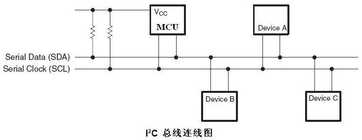
Its typical interface connections are as follows:
The I2C protocol is simple:
Data validity
When transferring data, the SDA line must be stable during the high period of the clock. The high or low state of SDA can only be changed when the clock signal of the SCL line is low.
Start and stop conditions
When the SCL line is high, the SDA line switches from high level to low level. This condition indicates the start condition;
When the SCL line is high, the SDA line switches from low to high. This condition indicates a stop condition.
Byte format
Each byte sent to the SDA line must be 8 bits, and the number of bytes that can be transmitted per transfer is not limited. A response bit must be processed after each byte.
Response response
The data transmission must be responsive and the associated response clock pulses are generated by the host. The transmitter releases the SDA line (high) during the responding clock pulse.
During the responding clock pulse, the receiver must pull the SDA line low to maintain a stable low level during the high period of this clock pulse.
That is to say, the master device receives an acknowledge bit (low level) after transmitting one byte of data, and sends a low level after the slave device receives a byte.
Addressing mode (7-bit address mode)
The first 7 bits of the first byte form the slave address, and the least significant bit (LSB) is the 8th bit, which determines the normal and extended 7-bit address format direction with repeated start conditions. The lowest bit of the first byte is
“0†means that the host will write information to the selected slave;
"1" means that the host will read the information to the slave. When an address is sent, each device in the system compares the first 7 bits with its own address after the start condition. If so, the device determines that it is addressed by the host. As for the slave receiver or slave The transmitter is determined by the R/W bit.
arbitration
I2C is the host bus, and each device can be a host, but there can only be one host at any one time.
Stm32 has at least one I2C interface, provides multi-master functions, can implement timing, protocol, arbitration and timing functions of all I2C buses, supports standard and fast transfer modes, and is compatible with SMBus 2.0.
Harbour Marine Diesel Generator
Harbour Marine Diesel Generator,Onshore Marine Generator,Offshore Marine Generator,Marine Engine
Jiangsu Vantek Power Machinery Co., Ltd , https://www.vantekpower.com