
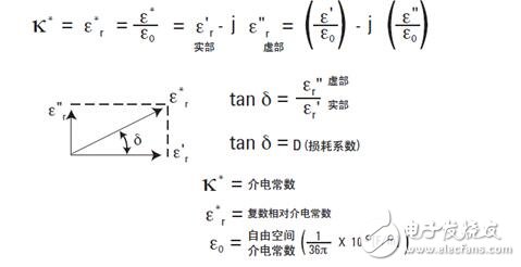
The dielectric constant describes the interaction between the material and the electric field. The dielectric constant (K*) is equal to the complex relative dielectric constant (ε*r), or the ratio of the complex dielectric constant (ε*) to the vacuum dielectric constant (ε0). The real part of the complex relative permittivity (ε'r) indicates how much electrical energy is stored in the material by the external electric field; for most solids and liquids, ε'r>1.
The imaginary part of the complex relative permittivity (ε "r) is called the loss factor, which indicates how much energy stored in the material is consumed or lost to the external electric field. ε"r is always >0, and is usually much smaller than ε'r. The loss factor includes both the effects of dielectric material loss and conductivity.
If a simple vector diagram is used to represent the complex dielectric constant, the phase of the real and imaginary parts will differ by 90°. Its vector sum forms an angle δ with the real axis (ε'r). The tangent tan δ or loss tangent of this angle is often used to indicate the relative "loss" of the material.
Measuring the dielectric constant using the parallel plate method
When measuring the dielectric constant using an impedance measuring instrument, the parallel plate method is usually employed.
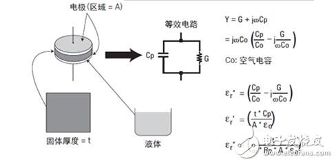
The parallel plate method is also called the three-terminal method in the ASTM D150 standard. The principle is to form a capacitor by inserting a material or a liquid sheet between two electrodes, and then measuring its capacitance, and calculating the dielectric constant based on the measurement result. In the actual test device, two electrodes were placed on a test fixture that holds the dielectric material. The impedance measuring instrument will measure the vector component of capacitance (C) and dissipation (D), and then calculate the dielectric constant and loss tangent by a software program.
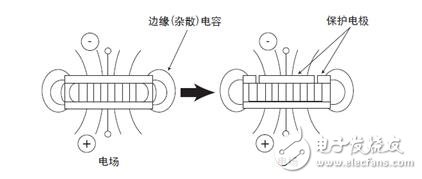
When the dielectric material between the two electrodes is simply measured, stray capacitance or edge capacitance is generated at the edge of the electrode, so that the measured capacitance value of the dielectric material is larger than the actual value. The edge capacitance causes current to flow through the dielectric material and the edge capacitor, resulting in measurement errors.
The use of a guard electrode eliminates measurement errors caused by edge capacitance. The guard electrode absorbs the electric field at the edge, so the capacitance measured between the electrodes is only formed by the current flowing through the dielectric material, so that accurate measurement results can be obtained. When the main electrode and the protective electrode are used in combination, the main electrode is referred to as a protected electrode.
Contact electrode method
This method derives the dielectric constant by measuring the capacitance of the electrode in direct contact with the material under test (MUT).
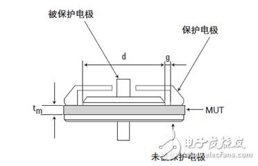
The dielectric constant and loss tangent are calculated by the following formula:
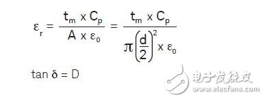
Where Cp: MUT equivalent parallel capacitance [F]
D: Dissipation coefficient (measured value)
Tm: average thickness of MUT [m]
A: Surface area of ​​the protected electrode [m2]
d: diameter of the protected electrode [m]
Ε0: dielectric constant of free space = 8.854 x 10⁻¹² [F/m]
The contact electrode method does not require the preparation of any material, and the measurement operation is very simple and thus the most widely used. However, when measuring in this way, if the air gap and its effects are not taken into account, serious measurement errors may occur.
When the electrode is in direct contact with the MUT, an air gap is formed between the MUT and the electrode. No matter how flat and parallel the two sides of the MUT are, it is inevitable that an air gap will be created. This air gap can cause errors in the measurement results because the measured capacitance is actually the capacitance of the dielectric material in series with the air gap.
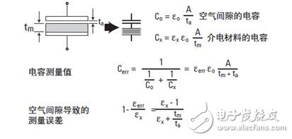
By contacting the surface of the dielectric material with a thin film electrode, the effect of the air gap can be reduced. Although additional material preparation (making a thin film electrode) is required, the most accurate measurement can be achieved.
Non-contact electrode method
The non-contact electrode method conceptually combines the advantages of the contact electrode method and avoids its disadvantages. It does not require a thin film electrode, but still solves the air gap effect. The dielectric constant is derived from the two capacitance measurements obtained with and without the MUT.
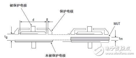
In theory, the electrode gap (tg) should be slightly smaller than the thickness (tm) of the MUT. In other words, the air gap (tg-tm) should be much smaller than the thickness (tm) of the MUT. These requirements must be met in order to perform measurements correctly. A minimum of two capacitance measurements are required to calculate the dielectric constant using the measurements.
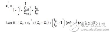
Where Cs1: Capacitance when no MUT is inserted [F]
Cs2: Capacitance when inserting MUT [F]
D1: Dissipation coefficient when MUT is not inserted
D2: Dissipation coefficient when inserting MUT
Tg : gap between protected/protected and unprotected electrodes [m]
Tm: average thickness of MUT [m]
Dielectric constant test methodIf you need to measure the dielectric constant of a solid material, such as ceramic materials. It needs to be measured using a dielectric thermometer. The test fixture in Sanqi Dielectric Thermometer is designed according to the international standard ASTM D150 method. The principle of parallel plate electrode is adopted. The test electrode consists of upper and lower electrodes + protective electrode. The upper and lower electrodes have good concentricity and parallelism, and the protective electrode can reduce the influence of the surrounding air capacitance, making the test data more accurate and reliable.
Therefore, samples should be prepared before measurement. To ensure the accuracy of the measurement results, sample preparation needs to follow the following points:
1, sample size: diameter 5-40mm (electrode diameter is 26.8mm), thickness less than 8mm;
2. The shape of the sample is prepared as a disc sample, and the electrodes are plated on both sides;
3, the surface of the sample must be smooth and smooth to ensure good contact with the parallel electrode. Otherwise, the measured capacitance value has an error in the value of the test due to the contact gap, which affects the test result.
Finally, the dielectric temperature spectrometer is used to automate the measurement of the high temperature dielectric constant of the material. Its measurement software can simultaneously measure and output frequency spectrum, voltage spectrum, bias spectrum, temperature spectrum, and dielectric temperature spectrum data. Support TXT, Excel, Bmp format export.
Shenzhen Sunbeam New Energy Co., Ltd , https://www.sunbeambattery.com