
Foreword:
Compared with helicopters, the four-rotor or even multi-rotor aircraft has a simple mechanical structure, flexible control, stable flight, smaller size, and of course greater capacity. It converts the complex mechanical structure design difficulty of helicopters into electronic circuits. And the algorithm above, so the design of the quadrotor is easier to get started and more popular.
The software core of the quadrotor includes two parts: the attitude fusion algorithm and the control algorithm; the hardware core is the MCU and the sensor.
First introduce the attitude fusion algorithm. The attitude fusion is to combine the 3-axis acceleration, the 3-axis angular velocity and the 3-axis magnetic field strength into a quaternion, and then convert the quaternion into Euler angles. Finally, the Euler angle is the most controlled. Delivered to all motors for the purpose of controlling the attitude of the aircraft. The Euler angle includes a yaw angle Yaw, a pitch angle Pitch, and a roll angle Roll. The algorithm I use is AHDSUpdate and IMUUpdate written by Madgwick. It is simple and effective. AHRSUpdate is a combination of gyroscope, accelerometer and magnetometer. IMUUpdate only combines gyroscope and accelerometer. In terms of advantages and disadvantages, IMUupdate algorithm only fuses. The accelerometer and gyroscope data also need to use a complementary filtering algorithm to fuse the magnetometer to correct the yaw angle Yaw, otherwise the aircraft will not find the north, but this complementary filtering has a small problem, that is, if the yaw angle is defined The range is 0-360 degrees, then when the nose is about 1 degree from north to west and 364 degrees north to east, the nose will pass 0 degrees (360 degrees), then yaw will not directly -0-364 changes so much, but it will be reversed from 1-20-180-270-364. This is a bad phenomenon. The experiment has not been solved for a long time, and AHRSupdate solved this very well. The problem, however, because AHRSupdate fuses the data of the magnetometer into all Euler angles, when the sensor is disturbed by the strong external magnetic field, it will cause a complete loss of control, resulting in a crash, and using the IMUupdate algorithm, at most
The sensor I used is the Invensense MPU9150 . The MPU9150 chip integrates accelerometer, gyroscope and magnetometer, and the built-in hardware DMP is used for attitude fusion, but it is not easy to use; the MCU is Gigadevice's GD32F103 series, because I am also Just in contact with the quadrotor, the first purpose is of course to be able to fly smoothly, without considering adding other peripherals. Follow-up may consider using GD32F107 or GD32F2xx series, expandable camera to play an aerial camera, of course, the better is GD32F4xx series (expected), comes with floating-point arithmetic unit, because my software is too dish, there are a lot of algorithms in the algorithm Floating point operations result in a low attitude update frequency and control frequency.
The four-axis aircraft is also for fun. At present, I have only completed the first step: attitude fusion. The next step is more important. Choose the appropriate rack, ESC, motor, propeller, write PID control code, and debug various parameters after system integration, anti-interference, anti-vibration, and finally add various application devices. . Encourage yourself here, insist on victory, and slowly grind the ocean.
I now implement the software functions: algorithm with AHRSupdate, gyroscope zero offset calibration, accelerometer smoothing filter, magnetometer plane calibration, later look at the situation may slowly update the accelerometer accurate calibration, magnetometer ellipsoid fitting calibration, gyroscope Temperature compensation, etc.
Part 1: Hardware
1. Sensor: MPU9150 (INVENSENSE company, integrated accelerometer, gyroscope and magnetometer in a single chip, and built-in DMP for attitude fusion, but only incorporates accelerometer and gyroscope, no fusion magnetometer, with The calibration function is much more expensive than the MPU6050, but saves PCB area, saves trouble, and has high axial coincidence. In fact, the MPU6050 and the magnetometer AK8975 are placed on the same chip. The program still uses the MPU6050 driver. The disadvantage is that it will be lost occasionally. Data, the update frequency of the built-in attitude fusion algorithm is not high);
2.MCU: GD32F103 CB (Gigadevice, ARMcortex-M3 core, 32-bit MCU, clocked at up to 108Mhz, 48Pin, directly compatible with ST's 32-bit MCU of the same model, more cost-effective, external 8M crystal, can also use internal 8M crystal oscillator, the crystal oscillator is far away from the sensor, to avoid interference with the magnetometer, but at the time it was not well thought out, the timer of this chip is too little, and GD32F103 VCT6 or GD32F107VCT6) will be adopted first;
3. Power chip: TLV70233DBVR (TI's LDO, input 2-6V, output 3.3V, only need two external X7R non-polar ceramic capacitors, the price is too high)
4. Serial port: MAX3232 (convenient to debug)
5.USB power supply, output voltage 5V
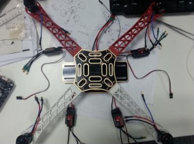
6. At present, the rack, ESC, battery, motor and propeller have been bought, and the picture is relatively popular:
Above:
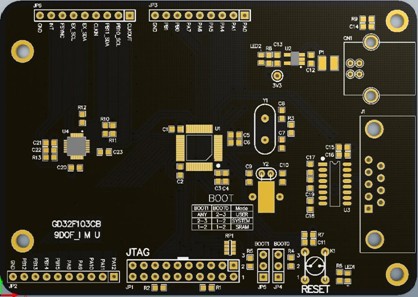
Figure 1: The 3D rendering of the PCB, the test version, the first pursuit of tuning to get the attitude angle, the subsequent revision will make a big adjustment:
Part II: Software
1. Use keil, uvision4.1.0, toolchain: RealViewMDK-ARM Version 4.12;
2. Driver: The official MPU6050 driver inv_mpu.c and inv_mpu_dmp_motion_driver.c;
Look at a few diagrams first, then the axis settings and algorithms section.
Above:
Figure 1: System initialization, the order from top to bottom is: initialize the MPU, set which sensors need to be used, set the gyroscope measurement range (I set the plus or minus 500 degrees / s), set the accelerometer measurement range (I set Is plus or minus 4g), configure fifo, set sampling rate, load DMP, set gyroscope axial (more important), enable some things of DMP, set DMP FIFO, self-calibration gyroscope and accelerometer, turn on DMP, Start the attitude fusion, see the following picture:
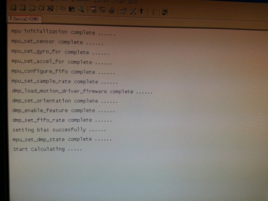
Figure 2: The final attitude angle obtained from the quaternion, where Yaw is the heading angle, indicating how many degrees the nose deviates from the north, Fan
Circumference -180 to +180; Pitch is the elevation angle, indicating the angle between the positive direction of the nose and the horizontal line, the range is -90 to +90; Roll is the tumbling angle, indicating the angle between the wing and the horizontal line, the range: -180 to + 180. The picture below shows the data of the fuselage level, and the nose is about 37 degrees west of the north:
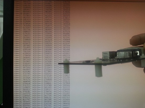
Figure 3: The figure below shows the level of the wing, the nose points to the north, and the nose is 25 degrees down.
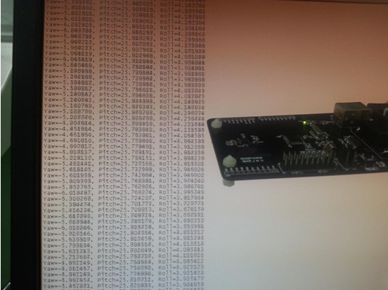
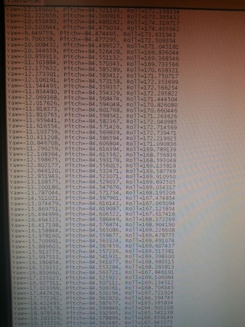
Figure 4: The figure below shows the head pointing to the north, keeping the level, and the right wing of the wing tilted down by 23 degrees.
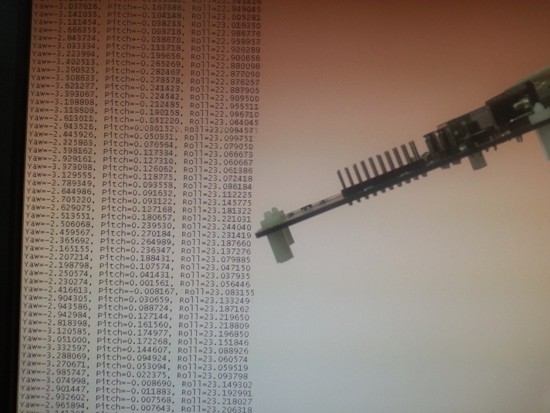
Figure 5: Looking at the singularity of the Euler angle, a rotational state at the singular point corresponds to an infinite number of degrees of freedom. When the object is turned around these singular points, there is no way to solve it. In the figure, when the Pitch is +90 degrees, the posture of the body cannot be controlled, and the axial direction of the Roll changes. As shown below:
Part III: How to determine your own axial direction
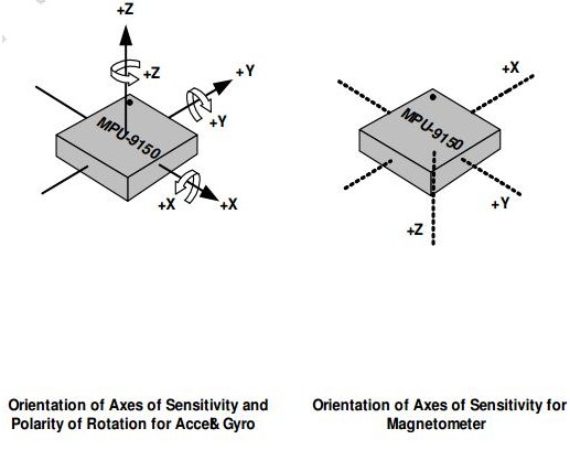
First, the definition of the axis is related to the initial quaternion and the Euler angle of the final settlement, and has nothing to do with the quaternion update algorithm. In other words, regardless of how your axis is defined, the pose fusion algorithm is used casually, but the quaternion is initialized. The formula for the number and the formula for the final settlement Euler angle are to be appropriately changed, as described in this latter algorithm. Accelerometers, gyroscopes, magnetometers, and their axial axes must satisfy the right-hand theorem, as shown below:
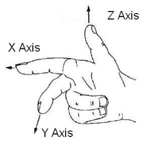
Attach a paragraph to explain how to define a reasonable axial direction, and how to properly rotate the axial direction of the sensor. Explaining so much is to say that the defined axial axis should satisfy the right-hand theorem, as shown below:

The figure below shows [xyz] before rotation and [-yxz] after rotation:
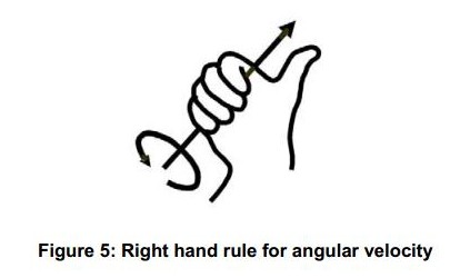
The figure below shows how to determine the positive direction of the rotation angle. Hold the coordinate axis with your right hand, the thumb points in the positive direction of the axis, and the direction in which the four fingers bend is the positive direction of the rotation angle. When the quaternion is initialized, the calculated The positive direction of the pull angle also satisfies this condition:
The axis used by my program is shown below, without any changes:
Part IV: Algorithm
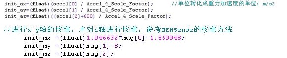
The first step is calibration, accelerometer and gyroscope. I use the MPU9150 internal self-calibration. The magnetometer is calibrated as follows: see attachment - magnetometer calibration
The second step is to initialize the quaternion. The common axial definition is that the rotation around the x-axis is Roll, the rotation around the y-axis is Pitch, and the rotation around the z-axis is Yaw. I have this definition in my program, but I commented it out. Here, another axial definition is given to explain the initialization quaternion, which is convenient for comparison. It is also the axis definition I am currently using.
Let us define that the rotation around the x-axis is Pitch, the rotation around the y-axis is Roll, and the rotation around the z-axis is Yaw. The positive direction of the axial direction is the same as above, unchanged.
First process the data of the accelerometer and magnetometer to get init_xx for us to use the following picture:
Then calculate the initialized Roll, Pitch, Yaw through the formula, pay attention to add a negative sign to ensure the positive direction of the rotation angle, as shown below:
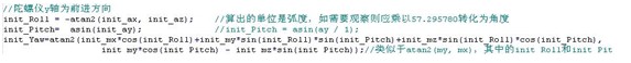
The direction of Yaw is not necessarily correct, you can verify it yourself. For details, see the attached-ST electronic compass to calculate Yaw.
Then the initial quaternion is obtained from the above Euler angle. At this time, we must pay attention to the difference of the rotation order. The formula is different. Most of the rotation order is ZYX. This order is also used in my program. Here we press ZXY. The order is rotated, and the formula for the quaternion is derived for comparison, and its rotation matrix:
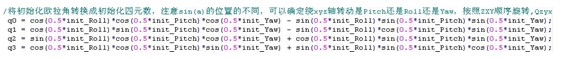
q=qyaw*qpitch*qroll=
(cos(0.5*Yaw)+ksin(0.5*Yaw)) *(cos(0.5*Pitch)+isin(0.5* Pitch)) * (cos(0.5*Roll)+jsin(0.5* Roll))
The formula for calculating the initial quaternion is as shown in the following figure:
The order in which i, j, and k are multiplied cannot be changed arbitrarily. The previous calculation is performed, and the formula for multiplication is calculated as follows:

At this point, the initialization quaternion is completed.
The third step is to use the AHRSUpdate algorithm. After using it, calculate the Euler angle according to the formula. This formula is related to the rotation order and the axis used for rotation. Our rotation order is ZXY, and the winding around Z is Yaw. Pitch, around Y is Roll, pushed to the process as shown below:
First, the three directions of the cosine matrix are obtained:
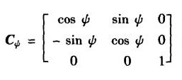
The following figure is around the Z axis Yaw:
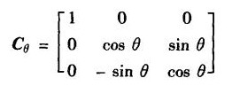
The following figure is around the X axis pitch:
The following figure rotates around the Y axis:

Then we find C=Croll * Cpitch * Cyaw according to our ZXY order, as shown below:
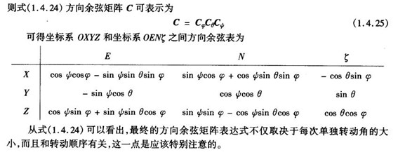
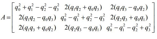
By comparing the direction cosine matrix C of the above figure with the quaternion attitude matrix of the following figure, the Euler angle can be obtained. Note that the direction of the cosine matrix C of the above figure changes as we define the axis. The quaternion pose matrix of the following figure is fixed:
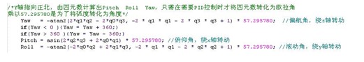
The final step is to find the Euler angle. The formula is as follows:
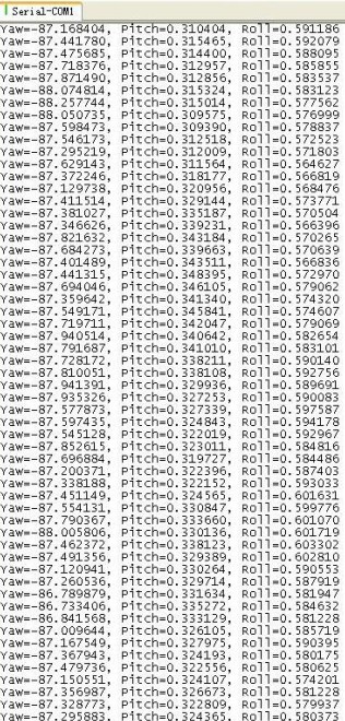
The following is the data when it is powered on at rest:
The following is the data after half an hour of power-on:
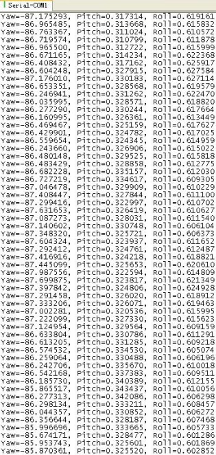
It can be seen that in the normal static state, the fluctuation range of the data is not more than 1 degree, and there is no drift. The specific effect also needs to be adjusted after the rack is flying up.
Finally, summarize:
In my code, 0°
Note that when running 108Mhz, you need to modify the delay function and serial port function, increase the value of the delay function to avoid I2C communication failure, modify the serial port function to avoid the serial port garbled problem under 108Mhz, the specific modification method refers to the forum top post http://bbs .21ic.com/iclist-182-1.html.
Finally, thank you to all those who have helped me.
CBD VAPE PEN
CBD VAPE PEN
Shenzhen Aierbaita Technology Co., Ltd. , https://www.aierbaitavape.com