
The first generation of the control system was produced from 1930 to 1940, and the main representative was the mechanical control technology represented by the base instrument. The second generation was born in 1950, mainly based on electrical control technology-based relay control technology and regulators represented by analog control technology. The current control system is the third generation control system. It was born in the 1970s. The main technical representatives are the distributed control system (DCS) for the process industry and the programmable controller (PLC) for the discrete industry. .
In order to properly understand the meaning of the control system, there are some terms that must be understood about the control, which is introduced here.
1I/O pointI/O points are the most frequently heard term when discussing control systems. It refers to the input/output point, I stands for INPUT, refers to the input, and O stands for OUTPUT, which refers to the output. The input/output is for the control system. The input refers to the measurement parameter that enters the control system from the instrument. The output refers to the parameter that is output from the control system to the actuator. One parameter is called a point. The size of a control system is sometimes determined by the number of I/O points it can control.
2 analog quantity and switching quantityAnother common term in control systems is analog and switching. Regardless of the input or output, one parameter is either an analog quantity or a switching quantity. Analog quantity means that the amount of control system is a continuous value that varies within a certain range, such as temperature, from 0-100 degrees, pressure from 0-10MPA, liquid level from 1-5 meters, and electric valve opening from 0- 100%, etc. These quantities are analog quantities. The switch quantity means that the physical quantity has only two states, such as the on and off states of the switch, the closing and opening of the relay, the opening and closing of the solenoid valve, and the like.
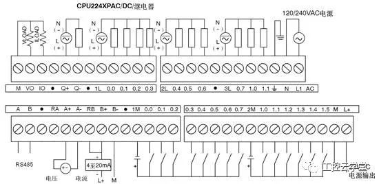
For the control system, since the CPU is binary, each bit of the data has two states of "0" and "1". Therefore, the switch quantity can be expressed by one bit inside the CPU, for example, with "0" On, use "1" to indicate off. The analog quantity is based on accuracy, and usually requires 8 to 16 to represent an analog quantity. The most common analog quantity is 12 bits, that is, the accuracy is 2-12, and the highest precision is about 2.5 parts per million. Of course, in practical control systems, the accuracy of the analog is limited by the accuracy of the analog/digital converters and meters, and it is usually impossible to achieve this.
3 control loop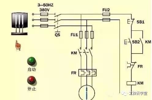
Usually for analog control, a controller determines an output according to an input quantity according to certain rules and algorithms, so that the input and output form a control loop. The control loop has the distinction between open loop and closed loop. The open loop control loop means that the output is based on a reference quantity, and there is no direct relationship between the input and output. The closed loop then feeds back the output of the control loop back as the input to the loop, compared to the setpoint value or the desired output value. Closed loop control, also known as feedback control, is the most common control method in control systems. Several conventional feedback control modes are described below.
Two-position controlThis is the simplest feedback control, sometimes called switch control. This control gives a signal to the switch when it is measured to the highest or lowest value. Although the measured quantity may be analog, the control output is switched, so it is called two-bit control. In the industrial field, there are many thermostats and level switch controls in this way.
Proportional controlThe output value of the controller is proportional to the measured value of the controlled parameter and the set value or the deviation of a certain reference point. The proportional control is smoother than the two-position control, eliminating the situation in which the controlled amount generated by the two-position control oscillates up and down. For example, if the liquid level of a reaction tank is set to 2700 mm, when the liquid level is lowered, the valve on the feed pipe will increase the opening, and when the liquid level is high, it will be opened. The degree is reduced. The ratio of increase and decrease is proportional to the deviation of the liquid level and the set value.
Integral controlIn the integral control, the change of the value of the controlled variable has a predetermined relationship with the time when the control system output control is actually effective. The output of the actuator is gradually reaching the set value. This type of control is generated because the actual control components and actuators often take a period of time from giving the output signal to bringing the controlled variable to the setpoint.
The most common example is temperature control. For example, suppose we know that when the gas valve is opened to 60%, the water temperature of the water heater can reach 45 degrees for a suitable bath, but when you screw the valve to 60% When the water is still cold, you have to wait, when the water temperature rises to about 45 degrees, it will be stable. If the control system does not use integral control, but only proportional control, then when the valve output is 60%, this is the input temperature value may still be only 20 degrees, then according to the proportional control, since the deviation still exists, the valve opening degree will Continue to increase, so that when the water temperature rises to 45 degrees, the valve opening may reach 90% or even higher. At this time, although the control system will notify the valve to remain stationary, the water temperature will continue to rise, possibly At 50 or even 60 degrees, the opening of the valve will decrease, but before the temperature is reduced to 60%, the water temperature will continue to rise. When the valve opening is reduced to 60%, the water temperature may still be 70 degrees. When the opening becomes 20%, the water temperature will become 45 degrees. At this time, the valve movement will stop, but the water temperature will continue to drop until it becomes cold water. If it is winter, your situation may be worse. This is what happens with temperature controllers without integral control. If you have a child, when the child first operates the valve of the water heater, what happens is like this.
Differential controlDifferential control is usually used simultaneously with proportional and integral control. Since the integral control has a hysteresis, the differential control allows the control to react to the deviation in advance, so that the control system's response is too slow. The use of differential control in conjunction with proportional and integral control allows the controlled state to reach a steady state more quickly without the above-mentioned oscillations.
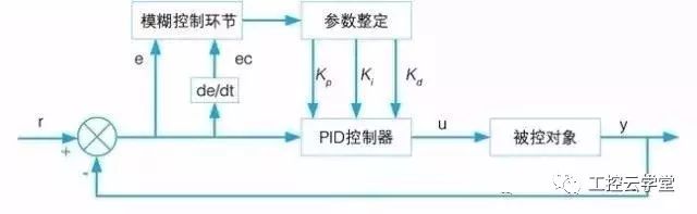
PID controlIn the actual control system, depending on the actual variables, the above three control methods sometimes have only one, sometimes two, and sometimes three. The proportional control is represented by P, the integral control is represented by I, and the differential control is represented by D, and is referred to as P control, PI control, and PID control according to the adopted mode. Among them, PID control is the most common control mode of the control system.
Usually used in the case of switching control, when a switch state changes (for example, when the switch is turned off), the output action of the controller is delayed for a while. For example, in a proximity switch commonly used in production lines, when the workpiece is in place, the proximity switch gives a signal, and the next roller has a distance from the position where the proximity switch is mounted, so it usually takes a few seconds to start scrolling.
Chain controlIt is also often used for switch control. For example, there are three switches, A, B and C. The C switch must be opened when A and B are simultaneously open; or C must be open when A is open; this relationship is interlocked. control. In industrial sites, especially where safety control is involved, interlocking controls are common. For example, the discharge valve in the reaction kettle, when the pressure reaches a certain value, the signal of the pressure switch changes, the release valve must be opened immediately.
Electric controlRefers to the output of the control system is carried out by electrical quantity or electronic signal, the object of control is electric actuators, such as relays, step switches, solenoid valves, servo drives and frequency converters, etc. There are some electric control components.
Hydraulic controlIn the operation of machines and equipment, many controls are carried out using hydraulic control mechanisms. In the case of continuous speed control, hydraulic control is usually convenient and cheap. When energy conversion efficiency is high, hydraulic control is often used simultaneously with servo control in electric control. At this time, an electro-hydraulic actuator with high efficiency and precision is formed.
There are three situations in which pneumatic actuators are used:
First, there is a standard one-way pneumatic valve combination on the moving line to complete the control logic function;
Second, in the gas pipeline, some components without moving parts are used, and these components are switched according to the characteristics of the gas flowing through;
Third, the motion logic control system uses modular built-in diaphragm, winding or sleeve type. All three pneumatic components use compressed air as the driving force for transmitting signals or executing mechanisms. In the factory, because compressed air is easy to obtain, clean, pollution-free, and safe, the functions and design of the control are very simple. Therefore, many production lines now use pneumatic tools.
Absolute rotary Encoder measure actual position by generating unique digital codes or bits (instead of pulses) that represent the encoder`s actual position. Single turn absolute encoders output codes that are repeated every full revolution and do not output data to indicate how many revolutions have been made. Multi-turn absolute encoders output a unique code for each shaft position through every rotation, up to 4096 revolutions. Unlike incremental encoders, absolute encoders will retain correct position even if power fails without homing at startup.
Absolute Encoder,Through Hollow Encoder,Absolute Encoder 13 Bit,14 Bit Optical Rotary Encoder
Jilin Lander Intelligent Technology Co., Ltd , https://www.jilinlandertech.com